BRAKE FLUID BLEEDING
CAUTION / NOTICE / HINT
Note
-
Move the shift lever to P and apply the parking brake before bleeding the brakes.
-
Add brake fluid to keep the level between the MIN and MAX lines of the reservoir while bleeding the brakes.
-
If brake fluid leaks onto any painted surface, immediately wash it off.
-
Do not operate the brake actuator assembly while air is in the brake system or in the brake master cylinder sub-assembly. Doing so may cause air to enter the brake actuator assembly.
-
If bleeding the brake actuator assembly is difficult due to air in the brake actuator assembly, replace it with a new one.
-
When bleeding air, select the suitable procedure listed below.
Replaced/Installed Item Work Procedure Flexible hose (front/rear) Bleed brake line Disc brake cylinder assembly (front/rear) Brake actuator assembly Bleed brake system Brake master cylinder sub-assembly Brake master cylinder reservoir assembly Brake booster assembly
Tech Tips
If any work is performed on the brake system or if air in the brake lines is suspected, bleed the air from the brake system.
PROCEDURE
-
BLEED BRAKE LINE
-
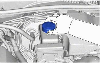
Remove the brake master cylinder reservoir filler cap assembly.
-
Add brake fluid to keep the level between the MIN and MAX lines of the reservoir while bleeding the brakes.
Brake Fluid SAE J1703 or FMVSS No. 116 DOT3 SAE J1704 or FMVSS No. 116 DOT4 Note
-
Make sure that there is sufficient brake fluid in the reservoir.
-
Do not remove the filter from the brake master cylinder reservoir assembly and be sure to fill the brake master cylinder reservoir assembly with new brake fluid to avoid any potential contamination of the brake system. Contamination, for example by dirt particles or mineral oil, could lead to functional brake problems.
-
-
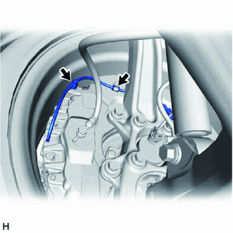
Disconnect the pad wear indicator wire assembly from the clamp of front disc brake dust cover.
-
Disconnect the bleeder plug cap portion of the front pad wear indicator wire assembly from the front disc brake bleeder plug.
-
Loosen the bleeder plug of the front disc brake cylinder assembly RH.
-
Repeatedly depress the brake pedal and bleed the air from the bleeder plug of the front disc brake cylinder assembly RH.
Note
Add brake fluid to keep the level between the MIN and MAX lines of the reservoir while bleeding the brake lines.
-
After all the air in the brake fluid is completely bled out, tighten the bleeder plug while depressing the brake pedal.
- Torque:
- 18.5 N*m { 189 kgf*cm, 14 ft.*lbf }
-
Bleed the air from the bleeder plug of the disc brake cylinder assembly LH using the same procedure as for the RH side.
-

*a 0° +/- 30° Connect the bleeder plug cap portion of the front pad wear indicator wire assembly to the front disc brake bleeder plug as shown in the illustration.
Note
Perform this step without the front pad wear indicator wire assembly installed to the front disc brake dust cover clamp.
-
Install the pad wear indicator wire assembly to the clamp of front disc brake dust cover.
-
Loosen the bleeder plug of the rear disc brake cylinder assembly RH.
-
Repeatedly depress the brake pedal and bleed the air from the bleeder plug of the rear disc brake cylinder assembly RH.
Note
Add brake fluid to keep the level between the MIN and MAX lines of the reservoir while bleeding the brake lines.
-
After all the air in the brake fluid is completely bled out, tighten the bleeder plug while depressing the brake pedal.
- Torque:
- 18.5 N*m { 189 kgf*cm, 14 ft.*lbf }
-
Bleed the air from the bleeder plug of the rear disc brake cylinder assembly LH using the same procedure as for the RH side.
-
Inspect for brake fluid leaks.
-
Inspect the brake fluid level in the reservoir.
-
Install the brake master cylinder reservoir filler cap assembly.
-
-
BLEED BRAKE SYSTEM
CAUTION:
If air is bled without using the GTS, damage or accidents may result. Therefore, always use the GTS when bleeding air.
Note
-
To prevent brake fluid from damaging painted surfaces, cover any surrounding parts with a piece of cloth.
-
Be sure to clean your hands before bleeding the brake master cylinder sub-assembly to avoid any potential contamination of the brake system. Contamination, for example by dirt particles or mineral oil, could lead to functional brake problems.
Tech Tips
If the brake master cylinder sub-assembly is reinstalled or runs out of brake fluid, bleed the brake master cylinder sub-assembly.
-
Remove the brake master cylinder reservoir filler cap assembly.
-
Add brake fluid to keep the level between the MIN and MAX lines of the reservoir while bleeding the brakes.
Brake Fluid SAE J1703 or FMVSS No. 116 DOT3 SAE J1704 or FMVSS No. 116 DOT4 Note
-
Make sure that there is sufficient brake fluid in the reservoir.
-
Do not remove the filter from the brake master cylinder reservoir and be sure to fill the brake master cylinder reservoir with new brake fluid to avoid any potential contamination of the brake system. Contamination, for example by dirt particles or mineral oil, could lead to functional brake problems.
-
-
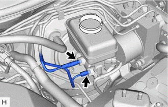
Using a union nut wrench, disconnect the 2 brake lines from the brake master cylinder sub-assembly.
Note
-
Do not kink or damage the brake lines.
-
Do not allow any foreign matter such as dirt or dust to enter the brake lines from the connecting parts.
-
-
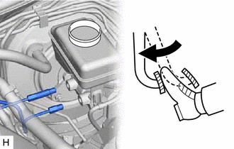
Slowly depress the brake pedal and hold it.*1
-
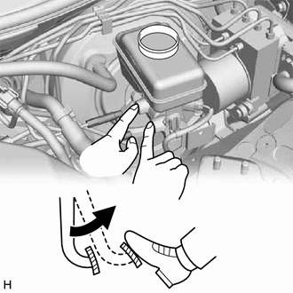
Cover the 2 outer holes with fingers, and release the brake pedal.*2
-
Repeat steps *1 and *2, 3 or 4 times.
-
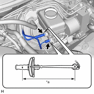
*a Torque Wrench Fulcrum Length Using a union nut wrench, connect the 2 brake lines to the brake master cylinder sub-assembly.
- Torque:
- Specified tightening torque
- 15.2 N*m { 155 kgf*cm, 11 ft.*lbf }
Note
-
Do not kink or damage the brake lines.
-
Do not allow the brake lines to twist or interfere with other parts or the vehicle body during tightening.
-
Do not allow any foreign matter such as dirt or dust to enter the brake lines from the connecting parts.
Tech Tips
-
Calculate the torque wrench reading when changing the fulcrum length of the torque wrench.
-
When using a union nut wrench (fulcrum length of 22 mm (0.866 in.)) + torque wrench (fulcrum length of 250 mm (9.84 in.)):
13.97 N*m (142 kgf*cm, 10 ft.*lbf)
-
Disconnect the front pad wear indicator wire assembly from the clamp of front disc brake dust cover.
-
Disconnect the bleeder plug cap portion of the front pad wear indicator wire assembly from the front disc brake bleeder plug.
-
Loosen the bleeder plug of the front disc brake cylinder assembly RH.
-
Repeatedly depress the brake pedal and bleed the air from the bleeder plug of the front disc brake cylinder assembly RH.
Note
Add brake fluid to keep the level between the MIN and MAX lines of the reservoir while bleeding the brake lines.
-
After all the air in the brake fluid is completely bled out, tighten the bleeder plug while depressing the brake pedal.
- Torque:
- 18.5 N*m { 189 kgf*cm, 14 ft.*lbf }
-
Bleed the air from the bleeder plug of the disc brake cylinder assembly LH using the same procedure as for the RH side.
-
Loosen the bleeder plug of the rear disc brake cylinder assembly RH.
-
Repeatedly depress the brake pedal and bleed the air from the bleeder plug of the rear disc brake cylinder assembly RH.
Note
Add brake fluid to keep the level between the MIN and MAX lines of the reservoir while bleeding the brake lines.
-
After all the air in the brake fluid is completely bled out, tighten the bleeder plug while depressing the brake pedal.
- Torque:
- 18.5 N*m { 189 kgf*cm, 14 ft.*lbf }
-
Bleed the air from the bleeder plug of the rear disc brake cylinder assembly LH using the same procedure as for the RH side.
-
Depress the brake pedal more than 20 times with the engine switch off.
-
Connect the GTS to the DLC3.
-
Turn the engine switch on (IG) and turn the GTS on.
Note
Do not start the engine.
-
Enter the following menus: Chassis / ABS/VSC/TRC / Utility / Air Bleeding.
Chassis > ABS/VSC/TRC > UtilityTester Display Air Bleeding -
Bleed the brake system following the instructions on the GTS.
-
After air bleeding, tighten each bleeder plug.
- Torque:
- 18.5 N*m { 189 kgf*cm, 14 ft.*lbf }
-
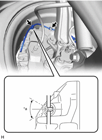
*a 0° +/- 30° Connect the bleeder plug cap portion of the pad wear indicator wire assembly to the front disc brake bleeder plug as shown in the illustration.
Note
Perform this step without the pad wear indicator wire assembly installed to the front disc brake dust cover clamp.
Tech Tips
-
Use the same procedure for the RH side and LH side.
-
The following procedure is for the LH side.
-
-
Install the front pad wear indicator wire assembly to the clamp of front disc brake dust cover.
-
Turn the GTS off and turn the engine switch off.
-
Disconnect the GTS from the DLC3.
-
Inspect for brake fluid leaks.
-
Inspect the brake fluid level in the reservoir.
-
Install the brake master cylinder reservoir filler cap assembly.
-