BRAKE ACTUATOR(for RHD) INSTALLATION
PROCEDURE
-
INSTALL BRAKE ACTUATOR BOLT CUSHION
-
Install the 3 brake actuator bolt cushions to the brake actuator bracket assembly.
-
-
INSTALL BRAKE ACTUATOR CASE COLLAR
-
Install the 3 brake actuator case collars to the brake actuator bolt cushions.
Note
Make sure the collars are in full contact with the cushions.
-
-
INSTALL BRAKE ACTUATOR BRACKET ASSEMBLY
-
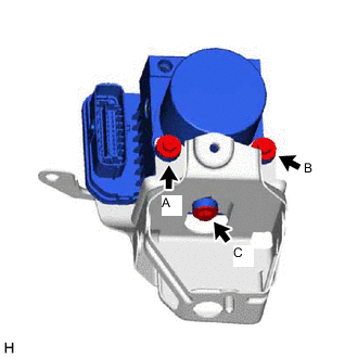
Temporarily install the brake actuator bracket assembly to the brake actuator with the 3 bolts.
Note
-
Do not remove the hole plugs of a new brake actuator before connecting the 6 brake lines because the brake actuator is filled with brake fluid.
-
Do not hold the actuator by the connector.
-
If the actuator is dropped, replace it.
-
-
Tighten the 3 bolts in the order shown in the illustration.
- Torque:
- 5.4 N*m { 55 kgf*cm, 48 in.*lbf }
-
-
INSTALL NO. 5 BRAKE ACTUATOR BRACKET
-
Install the No. 5 brake actuator bracket with the bolt.
- Torque:
- 11 N*m { 112 kgf*cm, 8 ft.*lbf }
-
-
INSTALL BRAKE ACTUATOR ASSEMBLY WITH BRACKET
-
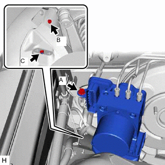
Temporarily install the brake actuator assembly with bracket with the 2 bolts and nut.
Note
-
Do not damage the brake tubes.
-
Do not hold the brake actuator assembly with bracket by the connector.
Tech Tips
Install the brake actuator assembly with bracket while avoiding the brake tubes.
-
-
Tighten the 2 bolts and nut in the order shown in the illustration.
- Torque:
- 19 N*m { 194 kgf*cm, 14 ft.*lbf }
-
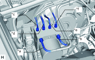
*a From Front Master Cylinder *b From Rear Master Cylinder *c To Front Wheel Cylinder Assembly RH *d To Front Wheel Cylinder Assembly RH *e To Rear Wheel Cylinder Assembly RH *f To Rear Wheel Cylinder Assembly LH Temporarily connect the 3 brake tubes to the correct positions on the brake actuator assembly as shown in the illustration.
-
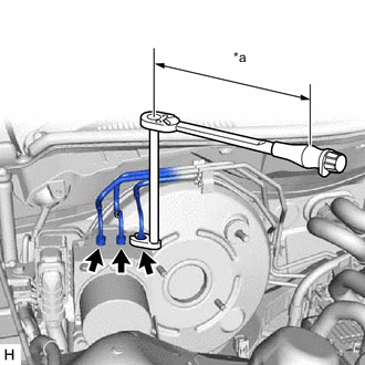
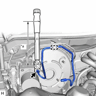
*a Torque Wrench Fulcrum Length Using a union nut wrench, fully tighten each brake tube.
- Torque:
- Specified tightening torque
- 15.2 N*m { 155 kgf*cm, 11 ft.*lbf }
Note
-
Do not kink or damage the brake tubes.
-
Do not allow the brake tubes to twist or interfere with other parts or the vehicle body during tightening.
-
Do not allow any foreign matter such as dirt or dust to enter the brake tubes from the connecting parts.
Tech Tips
-
Calculate the torque wrench reading when changing the fulcrum length of the torque wrench.
-
When using a union nut wrench (fulcrum length of 22 mm (0.866 in.)) + torque wrench (fulcrum length of 162 mm (6.378 in.)): 13.4 N*m (137 kgf*cm, 10 ft.*lbf)
-
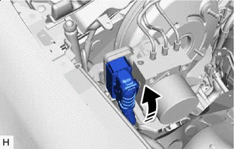

Lock Lever Locked Connect the connector to the brake actuator assembly and lock the lock lever.
Note
-
Make sure that the connector is locked securely.
-
Make sure that the actuator connector can be connected smoothly. Do not allow water, oil or dirt to enter the connector.
-
-
-
INSTALL REAR NO. 1 BRAKE TUBE
-
*a Torque Wrench Fulcrum Length Using a union nut wrench, connect the rear No. 1 brake tube to the brake actuator assembly.
- Torque:
- Specified tightening torque
- 19.5 N*m { 199 kgf*cm, 14 ft.*lbf }
Note
-
Do not kink or damage the rear No. 1 brake tube.
-
Do not allow the rear No. 1 brake tube to twist and interfere with other parts or vehicle body during tightening.
-
Do not allow any foreign matter such as dirt or dust to enter the rear No. 1 brake tube from the connecting parts.
Tech Tips
-
Calculate the torque wrench reading when changing the fulcrum length of the torque wrench Click here.
-
When using a union nut wrench (fulcrum length of 20 mm (0.787 in.)) + torque wrench (fulcrum length of 162 mm (6.378 in.)): 17.4 N*m (177 kgf*cm, 13 ft.*lbf)
-
Attach the clamp to install the rear No. 1 brake tube.
-
-
INSTALL FRONT NO. 1 BRAKE TUBE
-
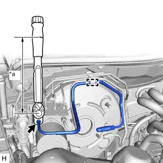
*a Torque Wrench Fulcrum Length Using a union nut wrench, connect the front No. 1 brake tube to the brake actuator assembly.
- Torque:
- Specified tightening torque
- 19.5 N*m { 199 kgf*cm, 14 ft.*lbf }
Note
-
Do not kink or damage the front No. 1 brake tube.
-
Do not allow the front No. 1 brake tube to twist and interfere with other parts or vehicle body during tightening.
-
Do not allow any foreign matter such as dirt or dust to enter the front No. 1 brake tube from the connecting parts.
Tech Tips
-
Calculate the torque wrench reading when changing the fulcrum length of the torque wrench Click here.
-
When using a union nut wrench (fulcrum length of 20 mm (0.787 in.)) + torque wrench (fulcrum length of 162 mm (6.378 in.)): 17.4 N*m (177 kgf*cm, 13 ft.*lbf)
-
Attach the clamp to install the front No. 1 brake tube.
-
-
CONNECT VACUUM HOSE ASSEMBLY
-
Connect the vacuum hose assembly to the brake vacuum check valve assembly, and slide the clip to secure it.
-
-
INSTALL BRAKE MASTER CYLINDER SUB-ASSEMBLY
-
INSTALL NO. 3 ENGINE ROOM RELAY BLOCK
-
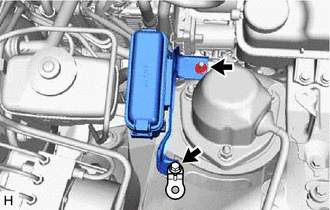
Install the No. 3 engine room relay block with the bolt and nut.
- Torque:
- 8.0 N*m { 82 kgf*cm, 71 in.*lbf }
-
-
CONNECT CABLE TO NEGATIVE BATTERY TERMINAL
Note
When disconnecting the cable, some systems need to be initialized after the cable is reconnected.
-
BLEED BRAKE SYSTEM
-
INSTALL FRONT WHEEL RH
-
REMOVE ENGINE ROOM SIDE COVER
-
Engage the guide to install the engine room side cover.
-
Install the 2 clips.
-
-
PERFORM YAW RATE AND ACCELERATION SENSOR AND ROLL RATE AND VERTICAL ACCELERATION SENSOR ZERO POINT CALIBRATION
-
PERFORM TEST MODE INSPECTION
-
INSPECT BRAKE ACTUATOR USING GTS
-
CHECK FOR AND CLEAR DTCS