BRAKE ACTUATOR(for RHD) REMOVAL
CAUTION / NOTICE / HINT
The necessary procedures (adjustment, calibration, initialization, or registration) that must be performed after parts are removed, installed, or replaced during the brake actuator assembly removal/installation are shown below.
| Replacement Part or Procedure | Necessary Procedures | Effects/Inoperative when not Performed | Link |
|---|---|---|---|
| Disconnect cable from negative battery terminal | Memorize steering angle neutral point | Parking assist monitor system | |
| Lane departure alert system (w/ Steering Control) | |||
| Pre-crash safety system | |||
| Adaptive high beam system | |||
| Reset power trunk lid | Power trunk lid system | ||
| Replacement of brake actuator assembly | Perform yaw rate and acceleration sensor and roll rate and vertical acceleration sensor zero point calibration and store system information |
|
CAUTION / NOTICE / HINT
Note
Make sure to release vacuum from the brake booster assembly before removing the brake master cylinder sub-assembly from the brake booster assembly.
PROCEDURE
-
PRECAUTION
Note
After turning the engine switch off, waiting time may be required before disconnecting the cable from the negative (-) battery terminal. Therefore, make sure to read the disconnecting the cable from the negative (-) battery terminal notices before proceeding with work.
-
DISCONNECT CABLE FROM NEGATIVE BATTERY TERMINAL
Note
When disconnecting the cable, some systems need to be initialized after the cable is reconnected.
-
REMOVE ENGINE ROOM SIDE COVER
-
Remove the 2 clips.
-
Disengage the guide to remove the engine room side cover.
-
-
REMOVE FRONT WHEEL RH
-
DRAIN BRAKE FLUID
Note
If brake fluid leaks onto any painted surface, immediately wash it off.
-
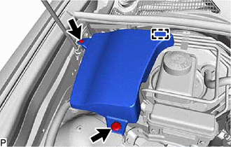
REMOVE NO. 3 ENGINE ROOM RELAY BLOCK
-
Remove the bolt, nut and disconnect the No. 3 engine room relay block.
-
-
REMOVE BRAKE MASTER CYLINDER SUB-ASSEMBLY
-
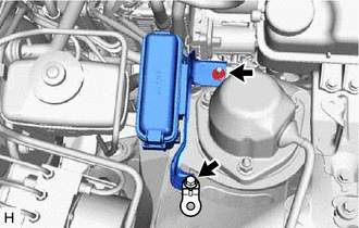
DISCONNECT VACUUM HOSE ASSEMBLY
-
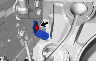
Slide the clip and disconnect the vacuum hose assembly from the brake vacuum check valve assembly.
-
-
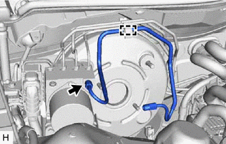
REMOVE FRONT NO.1 BRAKE TUBE
-
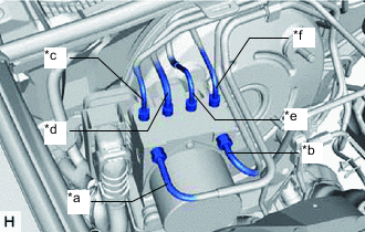
*a From Front Master Cylinder *b From Rear Master Cylinder *c To Front Wheel Cylinder Assembly RH *d To Front Wheel Cylinder Assembly LH *e To Rear Wheel Cylinder Assembly RH *f To Rear Wheel Cylinder Assembly LH Use tags or make a memo to identify the places to reconnect the brake tubes.
-
Using a union nut wrench, disconnect the front No. 1 brake tube from the brake actuator assembly.
Note
-
Do not kink or damage the front No. 1 brake tube.
-
Do not allow any foreign matter such as dirt or dust to enter the front No. 1 brake tube from the connecting parts.
-
-
Detach the clamp to remove the front No. 1 brake tube.
-
-
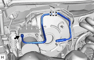
REMOVE REAR NO. 1 BRAKE TUBE
-
Using a union nut wrench, disconnect the rear No. 1 brake tube from the brake actuator assembly.
Note
-
Do not kink or damage the rear No. 1 brake tube.
-
Do not allow any foreign matter such as dirt or dust to enter the rear No. 1 brake tube from the connecting parts.
-
-
Detach the clamp to remove the rear No. 1 brake tube.
-
-
REMOVE BRAKE ACTUATOR ASSEMBLY WITH BRACKET
-
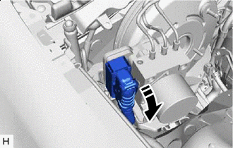

Lock Lever Released Release the lock lever and disconnect the connector from the brake actuator assembly.
Note
Be careful not to allow any brake fluid to enter the connector.
-
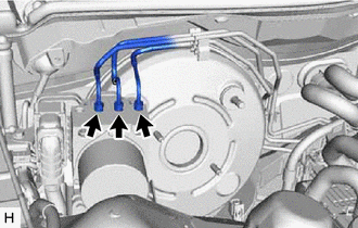
Using a union nut wrench, disconnect the 3 brake tubes from the brake actuator assembly.
-
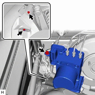
Remove the 2 bolts, nut and brake actuator assembly with bracket.
Note
-
Do not damage the brake tubes.
-
Do not hold the brake actuator assembly by the connector.
Tech Tips
Remove the brake actuator assembly with bracket while avoiding the brake tubes.
-
-
-
REMOVE NO. 5 BRAKE ACTUATOR BRACKET
-
Remove the bolt and No. 5 brake actuator bracket.
-
-
REMOVE BRAKE ACTUATOR BRACKET ASSEMBLY
-
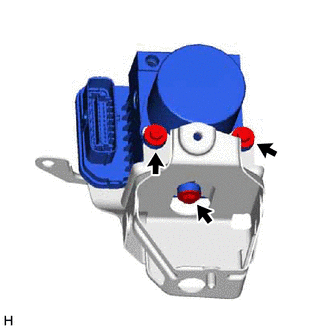
Remove the 3 bolts and brake actuator bracket assembly from the brake actuator assembly.
-
-
REMOVE BRAKE ACTUATOR CASE COLLAR
-
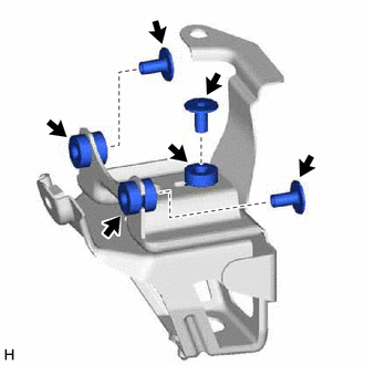
Remove the 3 brake actuator case collars from the brake actuator bolt cushions.
-
-
REMOVE BRAKE ACTUATOR BOLT CUSHION
-
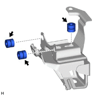
Remove the 3 brake actuator bolt cushions from the brake actuator bracket assembly.
-