BRAKE ACTUATOR(for LHD) REMOVAL
CAUTION / NOTICE / HINT
The necessary procedures (adjustment, calibration, initialization, or registration) that must be performed after parts are removed, installed, or replaced during the brake actuator assembly removal/installation are shown below.
| Replacement Part or Procedure | Necessary Procedure | Effect/Inoperative when not Performed | Link |
|---|---|---|---|
| Disconnect cable from negative battery terminal | Memorize steering angle neutral point | Parking assist monitor system | |
| Lane departure alert system (w/ Steering Control) | |||
| Pre-crash safety system | |||
| Adaptive high beam system | |||
| Reset power trunk lid | Power trunk lid system | ||
| Replacement of brake actuator assembly | Perform yaw rate and acceleration sensor and roll rate and vertical acceleration sensor zero point calibration and store system information |
|
CAUTION / NOTICE / HINT
Note
Make sure to release vacuum from the brake booster assembly before removing the brake master cylinder sub-assembly from the brake booster assembly.
PROCEDURE
-
PRECAUTION
Note
After turning the engine switch off, waiting time may be required before disconnecting the cable from the negative (-) battery terminal. Therefore, make sure to read the disconnecting the cable from the negative (-) battery terminal notices before proceeding with work.
-
DISCONNECT CABLE FROM NEGATIVE BATTERY TERMINAL
Note
When disconnecting the cable, some systems need to be initialized after the cable is reconnected.
-
REMOVE ENGINE ROOM SIDE COVER LH
-
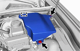
Remove the 2 clips.
-
Disengage the guide to remove the engine room side cover LH.
-
-
REMOVE FRONT WHEEL LH
-
DRAIN BRAKE FLUID
Note
If brake fluid leaks onto any painted surface, immediately wash it off.
-
REMOVE BRAKE MASTER CYLINDER SUB-ASSEMBLY
-
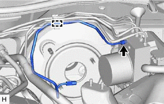
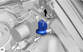
DISCONNECT UNION TO CHECK VALVE HOSE
-
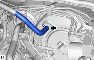
Slide the clip and disconnect the union to check valve hose from the brake booster assembly.
-
-
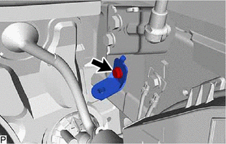
TEMPORARILY INSTALL BRAKE ACTUATOR ASSEMBLY WITH BRACKET
-
Temporarily install the brake actuator assembly with bracket with the 2 bolts and nut.
Note
-
Do not damage the brake tubes.
-
Do not hold the brake actuator assembly with bracket by the connector.
-
-
-
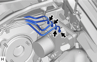
REMOVE FRONT NO. 1 BRAKE TUBE
-
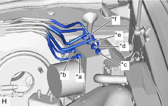
*a From 1st Chamber of Brake Master Cylinder Sub-assembly *b From 2nd Chamber of Brake Master Cylinder Sub-assembly *c To Front Wheel Cylinder Assembly RH *d To Front Wheel Cylinder Assembly LH *e To Rear Wheel Cylinder Assembly RH *f To Rear Wheel Cylinder Assembly LH Use tags or make a memo to identify the places to reconnect the brake tubes.
-
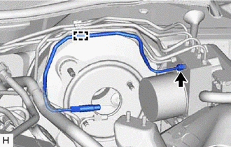
Using a union nut wrench, disconnect the front No. 1 brake tube from the brake actuator assembly.
Note
-
Do not kink or damage the front No. 1 brake tube.
-
Do not allow any foreign matter such as dirt or dust to enter the front No. 1 brake tube from the connecting parts.
-
-
Disengage the clamp to remove the front No. 1 brake tube.
-
-
REMOVE REAR NO. 1 BRAKE TUBE
-
Using a union nut wrench, disconnect the rear No. 1 brake tube from the brake actuator assembly.
Note
-
Do not kink or damage the rear No. 1 brake tube.
-
Do not allow any foreign matter such as dirt or dust to enter the rear No. 1 brake tube from the connecting parts.
-
-
Disengage the clamp to remove the rear No. 1 brake tube.
-
-
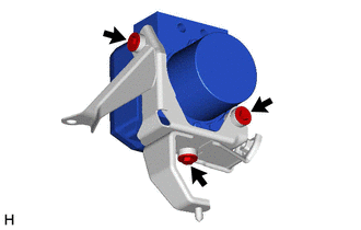
REMOVE BRAKE ACTUATOR ASSEMBLY WITH BRACKET
-

Release the lock lever 
Disconnect the connector Release the lock lever and disconnect the connector from the brake actuator assembly.
Note
Be careful not to allow any brake fluid to enter the connector.
-
Using a union nut wrench, disconnect the 4 brake tubes from the brake actuator assembly.
-
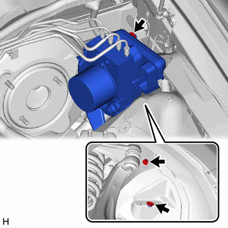
Remove the 2 bolts, nut and brake actuator assembly with bracket.
Note
-
Do not damage the brake tubes.
-
Do not hold the brake actuator assembly by the connector.
Tech Tips
Remove the brake actuator with bracket while avoiding the brake tubes.
-
-
-
REMOVE NO. 5 BRAKE ACTUATOR BRACKET
-
Remove the bolt and No. 5 brake actuator bracket.
-
-
REMOVE BRAKE ACTUATOR ASSEMBLY
-
Remove the 3 bolts and brake actuator assembly from the brake actuator bracket assembly.
-
-
REMOVE BRAKE ACTUATOR BOLT CUSHION
-
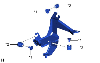
*1 Brake Actuator Case Collar *2 Brake Actuator Bolt Cushion Remove the 3 brake actuator case collars from the brake actuator bolt cushions.
-
Remove the 3 brake actuator bolt cushions from the brake actuator bracket assembly.
-