VEHICLE STABILITY CONTROL SYSTEM, Diagnostic DTC:C1380

| DTC Code | DTC Name |
|---|---|
| C1380 | Stop Light Control Relay Malfunction |
DESCRIPTION
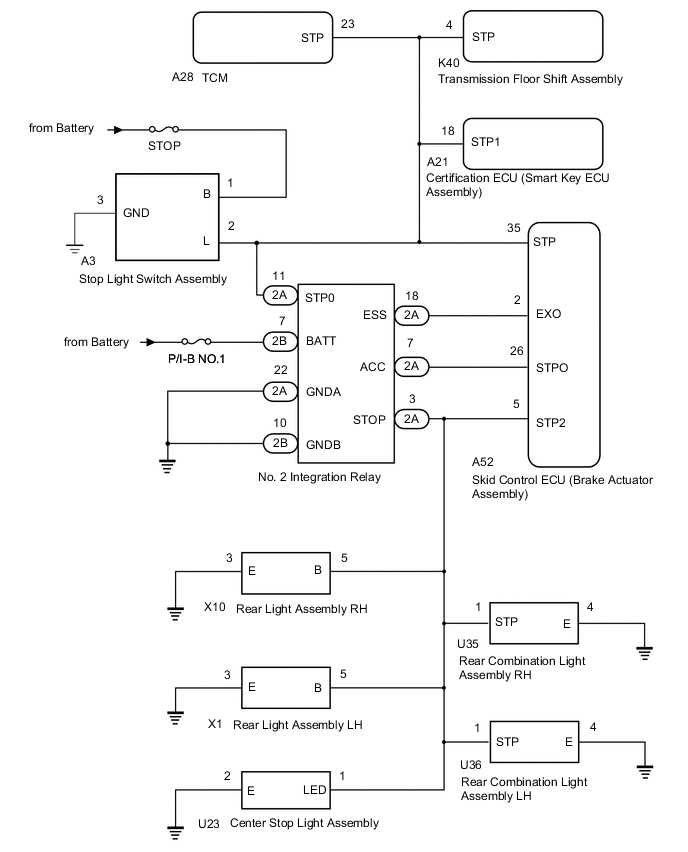
Upon receiving the brake hold control operating signal from the skid control ECU (brake actuator assembly), the relay contact turns on and the stop lights come on.
| DTC No. | Detection Item | DTC Detection Condition | Trouble Area | Note |
|---|---|---|---|---|
| C1380 | Stop Light Control Relay Malfunction |
|
|
- |
| Vehicle Condition | |||
|---|---|---|---|
| Pattern 1 | Pattern 2 | ||
| Diagnosis Condition | - | - | - |
| Malfunction Status | When the voltage at terminal +BS is 9.5 V or higher, stop light drive output (STPO) is ON, EXO is OFF and STP2 is OFF | ○ | - |
| When the voltage at terminal +BS is 9.5 V or higher, stop light drive output (STPO) is OFF, EXO is OFF and input signals for STP and STP2 differ | - | ○ | |
| Detection Time | 5 seconds or more. | 5 seconds or more. | |
| Number of Trips | 1 trip | 1 trip | |
Tech Tips
DTC will be output when conditions for either of the patterns in the table above are met.
WIRING DIAGRAM
CAUTION / NOTICE / HINT
Note
-
When replacing the skid control ECU (brake actuator assembly), perform zero point calibration and store system information.
-
Inspect the fuses for circuits related to this system before performing the following procedure.
-
Before replacing the certification ECU (smart key ECU assembly), refer to Service Bulletin.
Tech Tips
When C1425 is output together with C1380, inspect and repair the trouble areas indicated by C1425 first.
PROCEDURE
-
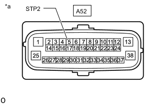
INSPECT TERMINAL VOLTAGE (SKID CONTROL ECU (BRAKE ACTUATOR ASSEMBLY) CONNECTOR)
-
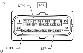
*a Front view of wire harness connector
(to Skid control ECU (Brake actuator assembly))
Make sure that there is no looseness at the locking part and the connecting part of the connector.
OK The connector is securely connected. -
Disconnect the A52 skid control ECU (brake actuator assembly) connector.
-
Check both the connector case and the terminals for deformation and corrosion.
OK No deformation or corrosion. -
Measure the voltage according to the value(s) in the table below.
Standard Voltage Tester Connection Condition Specified Condition A52-35 (STP) - Body ground Brake pedal depressed 8 to 14 V Brake pedal released Below 1.5 V A52-26 (STPO) - Body ground Engine switch on (IG) 11 to 14 V A52-5 (STP2) - Body ground Brake pedal depressed 8 to 14 V Brake pedal released Below 1.5 V Result Result Proceed to All terminal voltage is normal A Only STP terminal voltage abnormal B Only STPO terminal voltage abnormal C Only STP2 terminal voltage abnormal D STPO terminal and STP2 terminal voltage abnormal E
B 
CHECK HARNESS AND CONNECTOR (BRAKE ACTUATOR ASSEMBLY - TCM) Click here
C
CHECK HARNESS AND CONNECTOR (BRAKE ACTUATOR ASSEMBLY - NO. 2 INTEGRATION RELAY) Click here
D
CHECK HARNESS AND CONNECTOR (STOP LIGHT SWITCH ASSEMBLY - NO. 2 INTEGRATION RELAY) Click here
E
CHECK HARNESS AND CONNECTOR (NO. 2 INTEGRATION RELAY POWER SOURCE TERMINAL) Click here
A 
-
-
PERFORM ACTIVE TEST USING GTS (STOP LIGHT RELAY)
-
Reconnect the A52 skid control ECU (brake actuator assembly) connector.
-
Perform "Active Test" according to the display on the GTS.
Chassis > ABS/VSC/TRC > Active TestTester Display Measurement Item Control Range Diagnostic Note Stop Light Relay No. 2 integration relay Relay ON/OFF Stop lights come on
Chassis > ABS/VSC/TRC > Active TestTester Display Stop Light Relay -
According to the display on the GTS, perform the Active Test and check the operation of the stop lights.
OK Stop lights turn on/off in accordance with the Active Test. Result Proceed to OK NG
NG
INSPECT BRAKE ACTUATOR ASSEMBLY Click here
OK
-
-
RECONFIRM DTC
-
Clear the DTCs.
Chassis > ABS/VSC/TRC > Clear DTCs -
Perform "Active Test" according to the display on the GTS.
Chassis > ABS/VSC/TRC > Active TestTester Display Measurement Item Control Range Diagnostic Note Stop Light Relay No. 2 integration relay Relay ON/OFF Stop lights come on Vehicle condition: Vehicle stopped
Chassis > ABS/VSC/TRC > Active TestTester Display Stop Light Relay -
Check if the same DTC is recorded.
Chassis > ABS/VSC/TRC > Trouble CodesResult Result Proceed to DTC C1380 is not output. A DTC C1380 is output. (for LHD) B DTC C1380 is output. (for RHD) C
A 
USE SIMULATION METHOD TO CHECK Click here
B
REPLACE BRAKE ACTUATOR ASSEMBLY Click here
C
REPLACE BRAKE ACTUATOR ASSEMBLY Click here
-
-
INSPECT BRAKE ACTUATOR ASSEMBLY
-
Perform "Active Test" according to the display on the GTS.
Chassis > ABS/VSC/TRC > Active TestTester Display Measurement Item Control Range Diagnostic Note Stop Light Relay No. 2 integration relay Relay ON/OFF Stop lights come on
Chassis > ABS/VSC/TRC > Active TestTester Display Stop Light Relay -
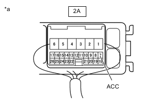
*a Component with harness connected (No. 2 integration relay) Measure the voltage according to the value(s) in the table below.
Standard Voltage Tester Connection Condition Specified Condition 2A-7 (ACC) - Body ground Active Test is ON Below 1.5 V Result Proceed to OK NG (for LHD) NG (for RHD)
OK
REPLACE NO. 2 INTEGRATION RELAY Click here
NG (for LHD)
REPLACE BRAKE ACTUATOR ASSEMBLY Click here
NG (for RHD)
REPLACE BRAKE ACTUATOR ASSEMBLY Click here
-
-
CHECK HARNESS AND CONNECTOR (BRAKE ACTUATOR ASSEMBLY - TCM)
-
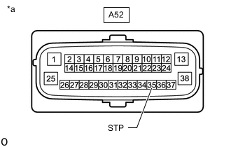
*a Front view of wire harness connector
(to Skid control ECU (Brake actuator assembly))
Make sure that there is no looseness at the locking part and the connecting part of the connector.
OK The connector is securely connected. -
Disconnect the A28 TCM connector.
-
Check both the connector case and the terminals for deformation and corrosion.
OK No deformation or corrosion. -
Measure the voltage according to the value(s) in the table below.
Standard Voltage Tester Connection Condition Specified Condition A52-35 (STP) - Body ground Brake pedal depressed 8 to 14 V A52-35 (STP) - Body ground Brake pedal released Below 1.5 V Result Proceed to OK NG
OK
REPLACE TCM Click here
NG
-
-
CHECK HARNESS AND CONNECTOR (BRAKE ACTUATOR ASSEMBLY - SHIFT LOCK CONTROL UNIT ASSEMBLY)
-
*a Front view of wire harness connector
(to Skid control ECU (Brake actuator assembly))
Make sure that there is no looseness at the locking part and the connecting part of the connector.
OK The connector is securely connected. -
Disconnect the K40 transmission floor shift assembly connector.
-
Check both the connector case and the terminals for deformation and corrosion.
OK No deformation or corrosion. -
Measure the voltage according to the value(s) in the table below.
Standard Voltage Tester Connection Condition Specified Condition A52-35 (STP) - Body ground Brake pedal depressed 8 to 14 V A52-35 (STP) - Body ground Brake pedal released Below 1.5 V Result Proceed to OK NG
OK
REPLACE TRANSMISSION FLOOR SHIFT ASSEMBLY Click here
NG
-
-
CHECK HARNESS AND CONNECTOR (BRAKE ACTUATOR ASSEMBLY - SMART KEY ECU ASSEMBLY)
-
*a Front view of wire harness connector
(to Skid control ECU (Brake actuator assembly))
Make sure that there is no looseness at the locking part and the connecting part of the connector.
OK The connector is securely connected. -
Disconnect the A21 certification ECU (smart key ECU assembly) connector.
-
Check both the connector case and the terminals for deformation and corrosion.
OK No deformation or corrosion. -
Measure the voltage according to the value(s) in the table below.
Standard Voltage Tester Connection Condition Specified Condition A52-35 (STP) - Body ground Brake pedal depressed 8 to 14 V A52-35 (STP) - Body ground Brake pedal released Below 1.5 V Result Proceed to OK NG
OK
REPLACE SMART KEY ECU ASSEMBLY
NG
CHECK WIRE HARNESS AND CONNECTOR (BRAKE ACTUATOR ASSEMBLY - NO. 2 INTEGRATION RELAY) Click here
-
-
CHECK HARNESS AND CONNECTOR (BRAKE ACTUATOR ASSEMBLY - NO. 2 INTEGRATION RELAY)
-
Make sure that there is no looseness at the locking part and the connecting part of the connector.
OK The connector is securely connected. -
Disconnect the 2A No. 2 integration relay connector.
-
Check both the connector case and the terminals for deformation and corrosion.
OK No deformation or corrosion. -
Measure the resistance according to the value(s) in the table below.
Standard Resistance Tester Connection Condition Specified Condition A52-26 (STPO) - 2A-7 (ACC) Always Below 1 Ω Result Proceed to OK NG
OK
REPLACE NO. 2 INTEGRATION RELAY Click here
NG
REPAIR OR REPLACE HARNESS OR CONNECTOR
-
-
CHECK WIRE HARNESS AND CONNECTOR (BRAKE ACTUATOR ASSEMBLY - NO. 2 INTEGRATION RELAY)
-
*a Front view of wire harness connector
(to Skid control ECU (Brake actuator assembly))
Make sure that there is no looseness at the locking part and the connecting part of the connector.
OK The connector is securely connected. -
Disconnect the 2A No. 2 integration relay connector.
-
Check both the connector case and the terminals for deformation and corrosion.
OK No deformation or corrosion. -
Measure the voltage according to the value(s) in the table below.
Standard Voltage Tester Connection Condition Specified Condition A52-35 (STP) - Body ground Brake pedal depressed 8 to 14 V A52-35 (STP) - Body ground Brake pedal released Below 1.5 V Result Proceed to OK NG
OK
REPLACE NO. 2 INTEGRATION RELAY Click here
NG
REPAIR OR REPLACE HARNESS OR CONNECTOR
-
-
CHECK HARNESS AND CONNECTOR (STOP LIGHT SWITCH ASSEMBLY - NO. 2 INTEGRATION RELAY)
-
Make sure that there is no looseness at the locking part and the connecting part of the connector.
OK The connector is securely connected. -
Disconnect the A3 stop light switch assembly connector.
-
Disconnect the 2A No. 2 integration relay connector.
-
Check both the connector case and the terminals for deformation and corrosion.
OK No deformation or corrosion. -
Measure the resistance according to the value(s) in the table below.
Standard Resistance Tester Connection Condition Specified Condition A3-2 (L) -2A-11 (STP0) Always Below 1 Ω Result Proceed to OK NG
NG
REPAIR OR REPLACE HARNESS OR CONNECTOR
OK
-
-
CHECK HARNESS AND CONNECTOR (BRAKE ACTUATOR ASSEMBLY - REAR LIGHT ASSEMBLY RH)
-
*a Front view of wire harness connector
(to Skid control ECU (Brake actuator assembly))
Make sure that there is no looseness at the locking part and the connecting part of the connector.
OK The connector is securely connected. -
Disconnect the X10 rear light assembly RH connector.
-
Check both the connector case and the terminals for deformation and corrosion.
OK No deformation or corrosion. -
Measure the voltage according to the value(s) in the table below.
Standard Voltage Tester Connection Condition Specified Condition A52-5 (STP2) - Body ground Stop light switch assembly on (Brake pedal depressed) 8 to 14 V A52-5 (STP2) - Body ground Stop light switch assembly off (Brake pedal released) Below 1.5 V Result Proceed to OK NG
OK
REPLACE REAR LIGHT ASSEMBLY RH Click here
NG
-
-
CHECK HARNESS AND CONNECTOR (BRAKE ACTUATOR ASSEMBLY - REAR LIGHT ASSEMBLY LH)
-
*a Front view of wire harness connector
(to Skid control ECU (Brake actuator assembly))
Make sure that there is no looseness at the locking part and the connecting part of the connector.
OK The connector is securely connected. -
Disconnect the X1 rear light assembly LH connector.
-
Check both the connector case and the terminals for deformation and corrosion.
OK No deformation or corrosion. -
Measure the voltage according to the value(s) in the table below.
Standard Voltage Tester Connection Condition Specified Condition A52-5 (STP2) - Body ground Stop light switch assembly on (Brake pedal depressed) 8 to 14 V A52-5 (STP2) - Body ground Stop light switch assembly off (Brake pedal released) Below 1.5 V Result Proceed to OK NG
OK
REPLACE REAR LIGHT ASSEMBLY LH Click here
NG
-
-
CHECK HARNESS AND CONNECTOR (BRAKE ACTUATOR ASSEMBLY - CENTER STOP LIGHT ASSEMBLY)
-
*a Front view of wire harness connector
(to Skid control ECU (Brake actuator assembly))
Make sure that there is no looseness at the locking part and the connecting part of the connector.
OK The connector is securely connected. -
Disconnect the U23 center stop light assembly connector.
-
Check both the connector case and the terminals for deformation and corrosion.
OK No deformation or corrosion. -
Measure the voltage according to the value(s) in the table below.
Standard Voltage Tester Connection Condition Specified Condition A52-5 (STP2) - Body ground Stop light switch assembly on (Brake pedal depressed) 8 to 14 V A52-5 (STP2) - Body ground Stop light switch assembly off (Brake pedal released) Below 1.5 V Result Proceed to OK NG
OK
REPLACE CENTER STOP LIGHT ASSEMBLY Click here
NG
-
-
CHECK HARNESS AND CONNECTOR (BRAKE ACTUATOR ASSEMBLY - REAR COMBINATION LIGHT ASSEMBLY RH)
-
*a Front view of wire harness connector
(to Skid control ECU (Brake actuator assembly))
Make sure that there is no looseness at the locking part and the connecting part of the connector.
OK The connector is securely connected. -
Disconnect the U35 rear combination light assembly RH connector.
-
Check both the connector case and the terminals for deformation and corrosion.
OK No deformation or corrosion. -
Measure the voltage according to the value(s) in the table below.
Standard Voltage Tester Connection Condition Specified Condition A52-5 (STP2) - Body ground Stop light switch assembly on (Brake pedal depressed) 8 to 14 V A52-5 (STP2) - Body ground Stop light switch assembly off (Brake pedal released) Below 1.5 V Result Proceed to OK NG
OK
REPLACE REAR COMBINATION LIGHT ASSEMBLY RH Click here
NG
CHECK HARNESS AND CONNECTOR (BRAKE ACTUATOR ASSEMBLY - REAR COMBINATION LIGHT ASSEMBLY LH) Click here
-
-
CHECK HARNESS AND CONNECTOR (NO. 2 INTEGRATION RELAY POWER SOURCE TERMINAL)
-
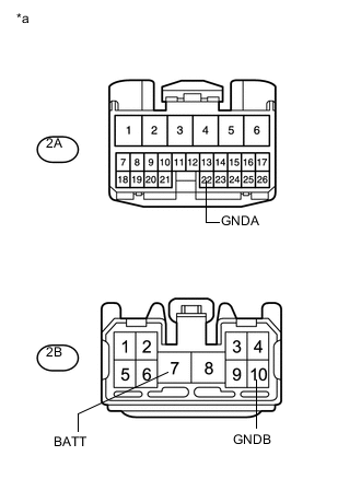
*a Front view of wire harness connector
(to No. 2 Integration Relay)
Turn the engine switch off.
-
Disconnect the 2A and 2B No. 2 integration relay connectors.
-
Measure the voltage according to the value(s) in the table below.
Standard Voltage Tester Connection Condition Specified Condition 2B-7 (BATT) - Body ground Always 11 to 14 V -
Measure the resistance according to the value(s) in the table below.
Standard Resistance Tester Connection Condition Specified Condition 2A-22 (GNDA) - Body ground Always Below 1 Ω 2B-10 (GNDB) - Body ground Always Below 1 Ω Text in Illustration *a Front view of wire harness connector
(to No. 2 Integration Relay)
Result Proceed to OK NG
NG
REPAIR OR REPLACE HARNESS OR CONNECTOR
OK
-
-
CHECK HARNESS AND CONNECTOR (BRAKE ACTUATOR ASSEMBLY - NO. 2 INTEGRATION RELAY)
-
Measure the resistance according to the value(s) in the table below.
Standard Resistance Tester Connection Condition Specified Condition A52-26 (STPO) or 2A-7 (ACC) - Body ground Always 10 kΩ or higher Result Proceed to OK NG
OK
REPLACE NO. 2 INTEGRATION RELAY Click here
NG
REPAIR OR REPLACE HARNESS OR CONNECTOR
-
-
CHECK HARNESS AND CONNECTOR (BRAKE ACTUATOR ASSEMBLY - REAR COMBINATION LIGHT ASSEMBLY LH)
-
*a Front view of wire harness connector
(to Skid control ECU (Brake actuator assembly))
Make sure that there is no looseness at the locking part and the connecting part of the connector.
OK The connector is securely connected. -
Disconnect the U36 rear combination light assembly LH connector.
-
Check both the connector case and the terminals for deformation and corrosion.
OK No deformation or corrosion. -
Measure the voltage according to the value(s) in the table below.
Standard Voltage Tester Connection Condition Specified Condition A52-5 (STP2) - Body ground Stop light switch assembly on (Brake pedal depressed) 8 to 14 V A52-5 (STP2) - Body ground Stop light switch assembly off (Brake pedal released) Below 1.5 V Result Proceed to OK NG
OK
REPLACE REAR COMBINATION LIGHT ASSEMBLY LH Click here
NG
-
-
CHECK HARNESS AND CONNECTOR (BRAKE ACTUATOR ASSEMBLY - NO. 2 INTEGRATION RELAY)
-
*a Front view of wire harness connector
(to Skid control ECU (Brake actuator assembly))
Make sure that there is no looseness at the locking part and the connecting part of the connector.
OK The connector is securely connected. -
Disconnect the 2A No. 2 integration relay connectors.
-
Check both the connector case and the terminals for deformation and corrosion.
OK No deformation or corrosion. -
Measure the resistance according to the value(s) in the table below.
Standard Voltage Tester Connection Condition Specified Condition A52-5 (STP2) - Body ground Always Below 1.5 V Result Proceed to OK NG
NG
REPAIR OR REPLACE HARNESS OR CONNECTOR
OK
-
-
CHECK HARNESS AND CONNECTOR (NO. 2 INTEGRATION RELAY POWER SOURCE TERMINAL)
-
*a Front view of wire harness connector
(to No. 2 Integration Relay)
Turn the engine switch off.
-
Disconnect the 2A and 2B No. 2 integration relay connectors.
-
Measure the voltage according to the value(s) in the table below.
Standard Voltage Tester Connection Condition Specified Condition 2B-7 (BATT) - Body ground Always 11 to 14 V -
Measure the resistance according to the value(s) in the table below.
Standard Resistance Tester Connection Condition Specified Condition 2A-22 (GNDA) - Body ground Always Below 1 Ω 2B-10 (GNDB) - Body ground Always Below 1 Ω Text in Illustration *a Front view of wire harness connector
(to No. 2 Integration Relay)
Result Proceed to OK NG
NG
REPAIR OR REPLACE HARNESS OR CONNECTOR
OK
-
-
CHECK HARNESS AND CONNECTOR (BRAKE BOOSTER WITH MASTER CYLINDER ASSEMBLY - STOP LIGHT SWITCH ASSEMBLY)
-
Measure the resistance according to the value(s) in the table below.
Standard Resistance Tester Connection Condition Specified Condition 2A-3 (STOP) - A52-5 (STP2) Always Below 1 Ω 2A-3 (STOP) or A52-5 (STP2) - Body ground Always 10 kΩ or higher Result Proceed to OK NG
OK
REPLACE NO. 2 INTEGRATION RELAY Click here
NG
REPAIR OR REPLACE HARNESS OR CONNECTOR
-