VEHICLE STABILITY CONTROL SYSTEM TC and CG Terminal Circuit
DESCRIPTION
Connecting terminals TC and CG of the DLC3 causes the ECU to display DTCs by blinking the ABS warning and slip indicator lights.
WIRING DIAGRAM
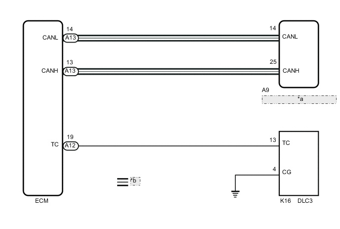
| *a | Skid Control ECU (Brake Actuator Assembly) |
| *b | CAN Communication Line |
CAUTION / NOTICE / HINT
Note
-
When replacing the skid control ECU (brake actuator assembly), perform zero point calibration and store system information.
-
Before replacing the ECM, refer to Service Bulletin.
Tech Tips
When the indicator lights continue to blink, a short to ground in the wiring of terminal TC of the DLC3 or an internal short to ground in one or more ECUs is suspected.
PROCEDURE
-
CHECK CAN COMMUNICATION SYSTEM
-
Check if CAN communication system DTCs are output.
for LHD: Click here
for RHD: Click here
Result Result Proceed to DTCs are not output. A DTCs are output. (for LHD) B DTCs are output. (for RHD) C
B 
INSPECT CAN COMMUNICATION SYSTEM for LHD: Click here
C
INSPECT CAN COMMUNICATION SYSTEM for RHD: Click here
A 
-
-
INSPECT DLC3
-
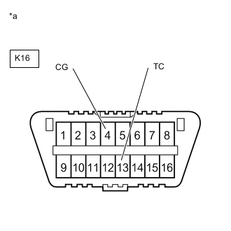
*a Front view of DLC3 Turn the engine switch on (IG).
-
Measure the voltage according to the value(s) in the table below.
Standard Voltage Tester Connection Switch Condition Specified Condition K16-13 (TC) - K16-4 (CG) Engine switch on (IG) 11 to 14 V Result Proceed to OK NG
NG 
CHECK HARNESS AND CONNECTOR (TC of DLC3 - ECM) Click here
OK
-
-
REPLACE ECM
-
*a Front view of DLC3 Turn the engine switch off.
-
Replace the ECM.
-
Using SST, connect terminals TC and CG of the DLC3.
- SST
- 09843-18040
-
Check that the ABS warning and slip indicator lights are blinking.
OK The ABS warning and slip indicator lights are blinking. Tech Tips
If troubleshooting has been carried out according to Problem Symptoms Table, refer back to the table and proceed to the next step before replacing parts.
Result Result Proceed to OK A NG (for LHD) B NG (for RHD) C
A
END
B
REPLACE BRAKE ACTUATOR ASSEMBLY for LHD: Click here
C
REPLACE BRAKE ACTUATOR ASSEMBLY for RHD: Click here
-
-
CHECK HARNESS AND CONNECTOR (TC of DLC3 - ECM)
-
Turn the engine switch off.
-
Disconnect the A77 ECM connector.
-
Measure the resistance according to the value(s) in the table below.
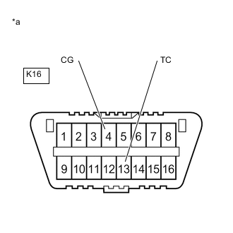
Standard Resistance Tester Connection Condition Specified Condition K16-13 (TC) - A12-19 (TC) Always Below 1 Ω K16-13 (TC) or A12-19 (TC) - Body ground Always 10 kΩ or higher Result Proceed to OK NG
NG
REPAIR OR REPLACE HARNESS OR CONNECTOR
OK
-
-
CHECK HARNESS AND CONNECTOR (CG of DLC3 - BODY GROUND)
-
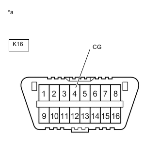
*a Front view of DLC3 Measure the resistance according to the value(s) in the table below.
Standard Resistance Tester Connection Condition Specified Condition K16-4 (CG) - Body ground Always Below 1 Ω Result Proceed to OK NG
NG
REPAIR OR REPLACE HARNESS OR CONNECTOR
OK
-
-
REPLACE ECM
-

*a Front view of DLC3 Replace the ECM.
-
Using SST, connect terminals TC and CG of the DLC3.
- SST
- 09843-18040
-
Check that the ABS warning and slip indicator lights are blinking.
OK The ABS warning and slip indicator lights are blinking. Tech Tips
If troubleshooting has been carried out according to Problem Symptoms Table, refer back to the table and proceed to the next step before replacing parts.
Result Result Proceed to OK A NG (for LHD) B NG (for RHD) C
A
END
B
REPLACE BRAKE ACTUATOR ASSEMBLY for LHD: Click here
C
REPLACE BRAKE ACTUATOR ASSEMBLY for RHD: Click here
-