VEHICLE STABILITY CONTROL SYSTEM PRECAUTION

-
TROUBLESHOOTING PRECAUTIONS
-
When there is a malfunction with terminal contact points or part installation problems, removal and installation of the suspected parts may return the system to normal either completely or temporarily.
-
In order to determine the malfunctioning area, be sure to check the conditions at the time the malfunction occurred, such as DTC output and Freeze Frame Data, and record it before disconnecting any connector or removing and installing parts.
-
Since the system may be influenced by malfunctions in systems other than the VSC system, be sure to check for DTCs in other systems.
-
-
HANDLING PRECAUTION
-
Do not remove or install VSC parts such as the steering angle sensor (spiral cable with sensor sub-assembly) or acceleration sensor (yaw rate sensor) except when required, as they need to be adjusted correctly after removal and installation.
-
Be sure to perform preparation before work and confirmation after work is completed by following the directions in the repair manual when working on the VSC system.
-
Be sure to remove and install the ECU, brake actuator assembly, sensors, etc. with the engine switch off unless it is otherwise specified in the inspection procedure.
-
If the ECU, brake actuator assembly or a sensor has been removed and installed, it is necessary to check the system for problems after the parts have been reassembled. Check for DTCs using the GTS. Also check that the system functions and signals received by the ECU are normal using Test Mode.
-
If replacing the skid control ECU (brake actuator assembly), always replace it with a new one (if the skid control ECU (brake actuator assembly) is not replaced with a new one, DTCs may be stored).
Note
Do not use a skid control ECU (brake actuator assembly) from another vehicle (a vehicle display model, etc.).
-
-
DTC PRECAUTION
-
Some DTCs cannot be cleared only by repairing the malfunctioning parts.
-
To turn off the warning (light illuminated), clear the DTC or perform the operation below.
Warning Clearing Procedure DTC No. Procedure C1243
C1245
C13AF
C1401
C1402
C1403
C1404
C1413
C1414
C1415
C1416
C1427
C146C
-
Repair or replace with new part
-
Turn power switch on (IG)
-
Drive (30 km/h or higher for 30 seconds) → Warning light turns off
C120B
C1380
C1422
C1423
C1424
C1426
C1430
C1431
-
Repair or replace with new part
-
Turn the power switch on (IG) and stop the vehicle for 5 seconds or more, and then lightly depress the brake pedal 2 or 3 times
-
At a vehicle speed of 50 km/h or higher, strongly depress the brake pedal for 3 seconds → Warning light turns off
Note
-
When a warning is output (light illuminated), the fail-safe function prevents system operation. Take due care when driving or braking.
-
Even after the DTC is cleared, the DTC will be stored again if the malfunction continues.
-
-
When 2 or more DTCs are detected, perform diagnosis for each DTC, one by one until the problem is identified.
-
-
CHASSIS DYNAMOMETER PRECAUTION
When testing with a 2-wheel drum tester such as a speedometer tester, combination tester for the speedometer and brakes, or chassis dynamometer, or when jacking up the front wheels and turning the wheels, perform the following procedure to enter Inspection Mode and disable the TRC and VSC systems.
Note
Secure the vehicle with lock chains for safety.
Tech Tips
-
If Inspection Mode is not used, the vehicle may unexpectedly move off the dynamometer because of TRC and VSC operation.
-
The VSC OFF switch (integration control and panel assembly) must not be used to disable TRC and VSC operation when the vehicle is to be operated on a dynamometer. Pressing the VSC OFF switch (integration control and panel assembly) does not disable TRC and VSC operation completely.
-
Activating Inspection Mode (When Using the GTS)
-
Ensure that the engine switch is off and the engine is stopped.
-
Connect the GTS to the DLC3.
-
Turn the engine switch on (IG).
-
Turn the GTS on.
-
Enter the following menus: Chassis / ABS/VSC/TRC / Utility / Inspection Mode.
Chassis > ABS/VSC/TRC > UtilityTester Display Inspection Mode -
Check that the VSC OFF and TRC OFF indicator lights come on.
Tech Tips
-
If the VSC OFF and TRC OFF indicator lights do not come on, repeat the steps above.
-
Using the GTS to cancel Inspection Mode causes the system to enter normal mode.
-
-
-
Activating Inspection Mode (When not Using the GTS)
Tech Tips
Perform steps "D" to "H" within 30 seconds.
-
Turn the engine switch on (IG) (Step "A").
-
Release the parking brake (Step "B").
-
Turn the engine switch off (Step "C").
-
With the brake pedal depressed, start the engine (Step "D").
-
While holding the brake pedal down, apply the parking brake (Step "E").
-
With the parking brake applied, depress and release the brake pedal twice (Step "F").
-
While holding the brake pedal down, release and apply the parking brake twice (Step "G").
-
With the parking brake applied, depress and release the brake pedal twice (Step "H").
-
Check if the VSC OFF and TRC OFF indicator lights comes on (Step "I").
Note
Turn the engine switch off when 60 seconds or more have elapsed since inspection mode was entered. If the engine switch is turned off before 60 seconds or more elapse, inspection modecontinues when the engine switch is turned on (IG).
Tech Tips
-
If the VSC OFF and TRC OFF indicator lights does not come on in step "I", repeat the steps from "A" to "I".
-
Turning the engine switch off ends Inspection Mode.
-
-
-
-
CAN COMMUNICATION SYSTEM PRECAUTIONS
-
The CAN communication system is used for communication between the skid control ECU (brake actuator assembly) the parking brake ECU assembly, roll rate and vertical acceleration sensor (yaw rate sensor), steering angle sensor (spiral cable with sensor sub-assembly), acceleration sensor (yaw rate sensor) and other ECUs. If there is trouble in a CAN communication line, corresponding DTCs in the communication line are output.
-
If any CAN communication DTCs are output, repair the malfunction, then troubleshoot the VSC system while communication is normal.
-
In order to enable CAN communication, a specific type of wiring is used for the CAN communication lines. The wiring used for each communication line is a twisted pair of wires that have an equal length.
A bypass wire should not be used because the data being transmitted will be corrupted.
-
-
CHASSIS DYNAMOMETER PRECAUTION
-
When using a drum tester, be sure to enter the VSC OFF mode to prohibit TRC and VSC control.
CAUTION:
-
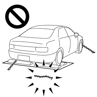
Do not use the drum tester with any of the lock chains disconnected.
-
Using the drum tester with a lock chain disconnected could cause the vehicle to begin moving unexpectedly.
-
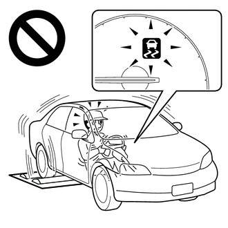
Do not use the drum tester while the TRC or VSC is able to operate.
-
TRC or VSC operation could cause the vehicle to begin moving unexpectedly.
-
-