TOE CONTROL LINK REMOVAL

CAUTION / NOTICE / HINT
The necessary procedures (adjustment, calibration, initialization, or registration) that must be performed after parts are removed, installed, or replaced during the rear suspension arm bracket assembly removal/installation are shown below.
| Replacement Part or Procedure | Necessary Procedure | Effect/Inoperative when not Performed | Link |
|---|---|---|---|
| Removal/installation of rear disc | Parking brake bedding | Electric parking brake system | |
| Rear wheel alignment adjustment |
|
|
|
| Removal/installation of rear height control sensor sub-assembly | Perform headlight control computer assembly LH initialization | Headlight leveling function |
PROCEDURE
-
REMOVE REAR WHEEL
-
SEPARATE REAR STEERING TIE ROD ASSEMBLY LH
-
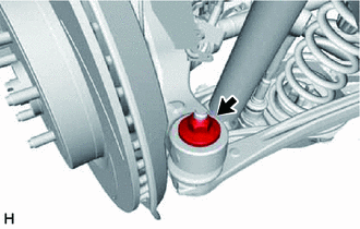
Remove the nut.
-
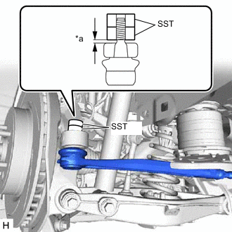
*a 1 mm (0.0394 in.) or more Install 2 spacers (SST spacer B) as shown in the illustration.
- SST
- 09960-20010 ( 09961-02060 )
Note
Make sure that the clearance between the rear axle assembly and spacers (SST spacer B) is 1 mm (0.0394 in.) or more to prevent damage to SST.
-
Using SST, separate the rear steering tie rod assembly LH from the rear axle assembly as shown in the illustration.
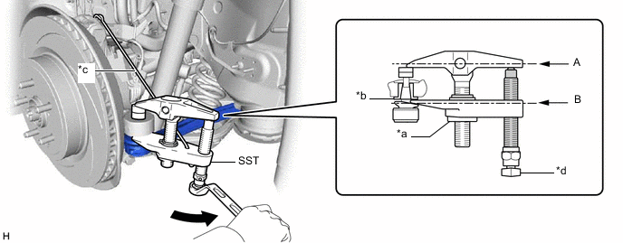
*a Nut *b Spacer *c Tie string without any slack *d Place wrench here 
Turn 
Molybdenum Grease - SST
- 09960-20010 ( 09961-02010, 09961-02060 )
Note
-
Apply molybdenum grease to the threads and tip of the SST bolt.
-
Install SST so that A and B are parallel.
-
Be sure to place the wrench on the part indicated in the illustration.
-
Be sure to tighten the string firmly to secure SST to the rear No. 2 upper control arm assembly LH to prevent SST from falling off.
-
Do not damage the rear steering tie rod assembly LH ball joint dust cover.
-
Make sure that SST is securely positioned on the spacer.
-
If the spacer has come off, replace the rear axle carrier sub-assembly with a new one.
-
-
SEPARATE REAR STEERING TIE ROD ASSEMBLY RH
Tech Tips
Perform the same procedure as for the LH side.
-
REMOVE REAR SUSPENSION MEMBER SUB-ASSEMBLY
-
REMOVE REAR SUSPENSION ARM BRACKET ASSEMBLY
-
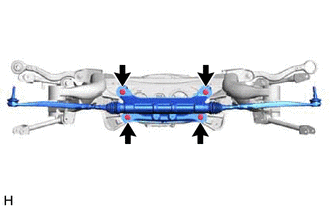
Remove the 4 bolts and rear suspension arm bracket assembly.
Note
Do not drop the rear suspension arm bracket assembly.
-
-
REMOVE REAR STEERING TIE ROD ASSEMBLY LH
-
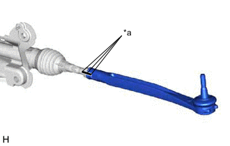
*a Matchmark Put matchmarks on the rear steering tie rod assembly LH, lock nut and steering rack end.
-
Remove the rear steering tie rod assembly LH and lock nut.
-
-
REMOVE REAR STEERING TIE ROD ASSEMBLY RH
Tech Tips
Perform the same procedure as for the LH side.