REAR LOWER ARM REMOVAL
CAUTION / NOTICE / HINT
The necessary procedures (adjustment, calibration, initialization, or registration) that must be performed after parts are removed, installed, or replaced during the rear No. 1 suspension arm assembly or rear No. 2 suspension arm assembly removal/installation are shown below.
| Replacement Part or Procedure | Necessary Procedure | Effect/Inoperative when not Performed | Link |
|---|---|---|---|
| Rear wheel alignment adjustment |
|
|
|
| Removal/installation of rear height control sensor sub-assembly | Perform headlight control computer assembly LH initialization | Headlight leveling function |
Tech Tips
-
Use the same procedure for the RH side and LH side.
-
The following procedure is for the LH side.
PROCEDURE
-
REMOVE REAR WHEEL
-
REMOVE REAR SUSPENSION ARM COVER
-
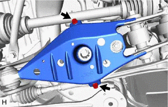
Remove the 2 bolts and rear suspension arm cover from the rear No. 2 suspension arm assembly.
-
-
SEPARATE REAR HEIGHT CONTROL SENSOR SUB-ASSEMBLY
-
SEPARATE REAR STEERING TIE ROD ASSEMBLY
-
REMOVE REAR NO. 1 SUSPENSION ARM ASSEMBLY
-
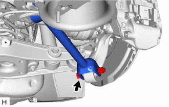
Remove the bolt and nut, and separate the rear No. 1 suspension arm assembly from the rear axle assembly.
Note
Because the nut has its own stopper, do not turn the nut. Loosen the bolt with the nut secured.
-
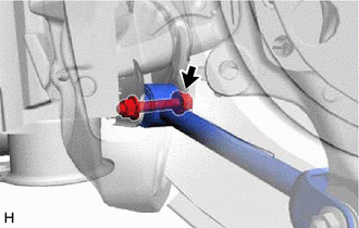
Remove the bolt and nut, and remove the rear No. 1 suspension arm assembly from the rear suspension member sub-assembly.
Note
Because the nut has its own stopper, do not turn the nut. Loosen the bolt with the nut secured.
-
-
REMOVE REAR STABILIZER LINK ASSEMBLY
-
SEPARATE REAR SHOCK ABSORBER ASSEMBLY
-
REMOVE REAR COIL SPRING
-
REMOVE REAR UPPER COIL SPRING INSULATOR
-
REMOVE REAR LOWER COIL SPRING INSULATOR
-
REMOVE REAR NO. 2 SUSPENSION ARM ASSEMBLY
-
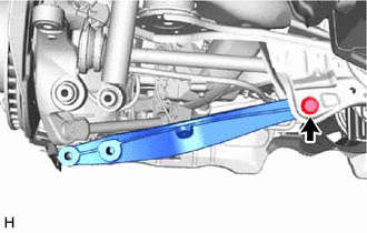
Remove the bolt, nut and rear No. 2 suspension arm assembly from the rear suspension member sub-assembly.
Note
Because the nut has its own stopper, do not turn the nut. Loosen the bolt with the nut secured.
-