REAR UPPER ARM REMOVAL
CAUTION / NOTICE / HINT
The necessary procedures (adjustment, calibration, initialization, or registration) that must be performed after parts are removed, installed, or replaced during the rear No. 1 upper control arm assembly or rear No. 2 upper control arm assembly removal/installation are shown below.
| Replacement Part or Procedure | Necessary Procedure | Effect/Inoperative when not Performed | Link |
|---|---|---|---|
| Removal/installation of rear disc | Parking brake bedding | Electric parking brake system | |
| Rear wheel alignment adjustment |
|
|
|
| Removal/installation of rear height control sensor sub-assembly | Perform headlight control computer assembly LH initialization | Headlight leveling function |
Tech Tips
-
Use the same procedure for the RH side and LH side.
-
The following procedure is for the LH side.
PROCEDURE
-
REMOVE REAR SUSPENSION MEMBER SUB-ASSEMBLY
-
REMOVE REAR NO. 1 UPPER CONTROL ARM ASSEMBLY
-
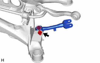
Remove the bolt, nut, washer and rear No. 1 upper control arm assembly from the rear suspension member sub-assembly.
Note
Because the bolt has its own stopper, do not turn the bolt. Loosen the nut with the bolt secured.
-
-
REMOVE REAR NO. 2 UPPER CONTROL ARM ASSEMBLY
-
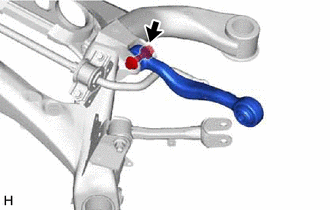
Remove the bolt, nut, washer and rear No. 2 upper control arm assembly from the rear suspension member sub-assembly.
Note
Because the bolt has its own stopper, do not turn the bolt. Loosen the nut with the bolt secured.
-