REAR COIL SPRING REMOVAL

CAUTION / NOTICE / HINT
The necessary procedures (adjustment, calibration, initialization, or registration) that must be performed after parts are removed, installed, or replaced during the rear coil spring removal/installation are shown below.
| Replacement Part or Procedure | Necessary Procedure | Effect/Inoperative when not Performed | Link |
|---|---|---|---|
| Rear wheel alignment adjustment |
|
|
|
| Removal/installation of rear height control sensor sub-assembly | Perform headlight control computer assembly LH initialization | Headlight leveling function |
Tech Tips
-
Use the same procedure for the RH side and LH side.
-
The following procedure is for the LH side.
PROCEDURE
-
REMOVE REAR WHEEL
-
REMOVE REAR SUSPENSION ARM COVER
-
SEPARATE REAR HEIGHT CONTROL SENSOR SUB-ASSEMBLY
-
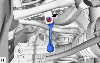
Remove the nut and separate the rear height control sensor sub-assembly from the rear No. 1 upper control arm assembly.
-
-
SEPARATE REAR STEERING TIE ROD ASSEMBLY
-
SEPARATE REAR NO. 1 SUSPENSION ARM ASSEMBLY
-
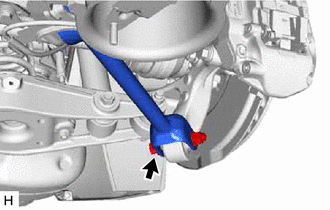
Remove the bolt and nut, and separate the rear No. 1 suspension arm assembly from the rear axle assembly.
Note
Because the nut has its own stopper, do not turn the nut. Loosen the bolt with the nut secured.
-
-
REMOVE REAR STABILIZER LINK ASSEMBLY
-
SEPARATE REAR SHOCK ABSORBER ASSEMBLY
-
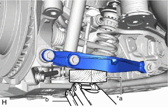
*a Wooden Block *b Jack Support the rear No. 2 suspension arm assembly using a jack and wooden block.
Note
-
When jacking up the rear No. 2 suspension arm assembly, be sure to jack it up slowly.
-
Make sure to perform this operation with the vehicle kept as low as possible.
-
-
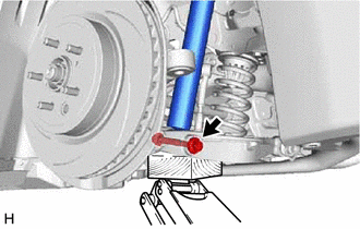
Remove the bolt and nut, and separate the rear shock absorber assembly from the rear No. 2 suspension arm assembly.
Note
Because the nut has its own stopper, do not turn the nut. Loosen the bolt with the nut secured.
-
-
REMOVE REAR COIL SPRING
-
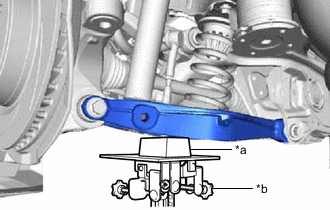
*a Wooden Block *b Transmission Jack Support the rear No. 2 suspension arm assembly using a transmission jack and wooden block.
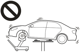
CAUTION:
-
Do not raise the jack up too high.
-
The vehicle could fall, resulting in a serious accident.
Note
-
When jacking up the rear No. 2 suspension arm assembly, be sure to jack it up slowly.
-
Make sure to perform this operation with the vehicle kept as low as possible.
-
-
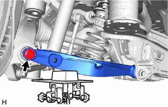
Loosen the rear No. 2 suspension arm assembly with the bolt (rear axle assembly side).
Note
-
Because the nut has its own stopper, do not turn the nut. Loosen the bolt with the nut secured.
-
Do not remove the bolt and nut.
-
-
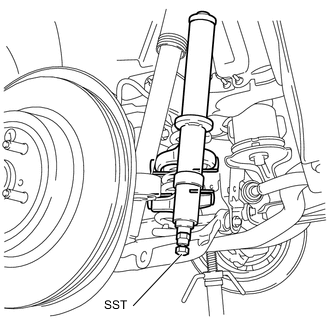
Attach the hooks of each SST arm across the diameter of the rear coil spring.
- SST
- 09727-00120
- 09727-30022 ( 09727-00010, 09727-00031 )
CAUTION:
-
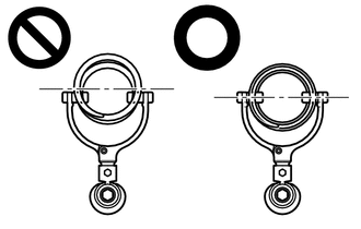
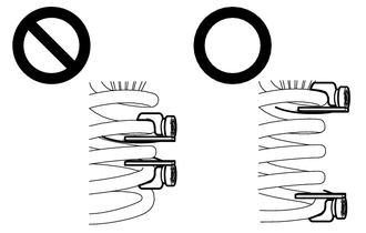
Do not perform the work without checking to make sure that the claws of the hooks are securely engaged.
-
It could cause the hook to slip off and the spring to fly out, which could result in an injury.
-
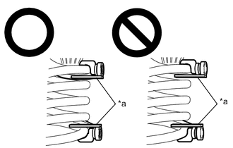
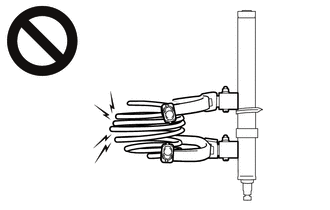
Make sure that the hooks of the upper and lower arms are attached to the coil spring so that the distance between the hooks is as large as possible.
-
It could cause the hook to slip off and the spring to fly out, which could result in an injury.
-
*a Stopper Plate Install the stopper plates to the hooks of SST.
CAUTION:
-
Make sure that the stopper plates are installed securely.
-
It could cause the hook to slip off and the spring to fly out, which could result in an injury.
-
-
Using SST, compress the rear coil spring.
CAUTION:
-
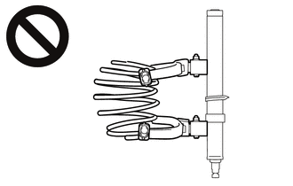
If the coil spring bends while using SST, stop immediately and reattach SST correctly.
-
It could cause the hook to slip off and the spring to fly out, which could result in an injury.
-
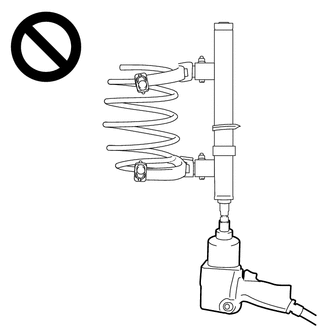
Do not compress the coil spring to the point where the coils touch each other.
-
It could cause the hook to slip off and the spring to fly out, which could result in an injury.
-
Do not use an impact wrench.
-
The threads may be stripped, or the sudden compression may result in slack that causes the hooks to slip off, causing the spring to fly out and possibly resulting in injury.
-
-
Remove the bolt and nut, and separate the rear No. 2 suspension arm assembly from the rear axle assembly.
Note
Because the nut has its own stopper, do not turn the nut. Loosen the bolt with the nut secured.
-
Slowly lower the rear No. 2 suspension arm assembly, and remove the rear coil spring with SST and rear upper coil spring insulator.
-
Remove SST from the rear coil spring.
Note
Do not use an impact wrench. It will damage SST.
-
-
REMOVE REAR UPPER COIL SPRING INSULATOR
-
Remove the rear upper coil spring insulator from the rear coil spring.
-
-
REMOVE REAR LOWER COIL SPRING INSULATOR
-
Remove the rear lower coil spring insulator from the rear No. 2 suspension arm assembly.
-