REAR SHOCK ABSORBER INSTALLATION
CAUTION / NOTICE / HINT
Tech Tips
-
Use the same procedure for the RH side and LH side.
-
The following procedure is for the LH side.
PROCEDURE
-
INSTALL REAR NO. 1 SPRING BUMPER
-
Install the rear No. 1 spring bumper to the rear shock absorber assembly.
-
-
INSTALL REAR SUSPENSION SUPPORT ASSEMBLY
-
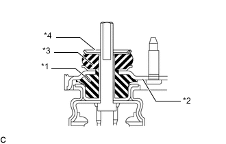
*1 Rear No. 2 Shock Absorber Cushion *2 Rear Suspension Support Assembly *3 Rear No. 1 Shock Absorber Cushion *4 Rear Shock Absorber Cushion Washer Install the rear No. 2 shock absorber cushion, rear suspension support assembly, rear No. 1 shock absorber cushion and rear shock absorber cushion washer to the rear shock absorber assembly.
Note
Be sure to install the rear shock absorber cushion washer in the correct direction.
-
Temporarily tighten a new rear support to rear shock absorber nut.
-
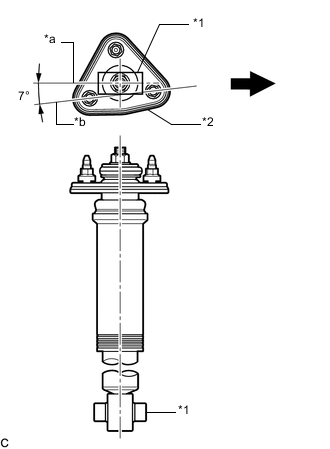
*1 Rear Shock Absorber Lower Bushing *2 Rear Suspension Support Assembly *a Rear Shock Absorber Lower Bushing Axis Line *b Rear Suspension Support Assembly Stud (Toward Vehicle Interior) 2-point Axis Line 
Front of the Vehicle Align the rear suspension support assembly so that the stud bolts of the rear suspension support assembly are positioned as shown in the illustration.
-
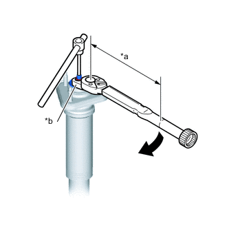
*a Torque Wrench Fulcrum Length *b Union Nut Wrench Using a union nut wrench, fully tighten the rear support to rear shock absorber nut while holding the rod of the rear shock absorber assembly with a 6 mm hexagon socket wrench.
- Torque:
- Specified tightening torque
- 18 N*m { 184 kgf*cm, 13 ft.*lbf }
Note
Securely insert the 6 mm hexagon socket wrench into the rear shock absorber rod to prevent damage to the rear shock absorber assembly when tightening the rear support to rear shock absorber nut.
Tech Tips
-
Calculate the torque wrench reading when changing the fulcrum length of the torque wrench.
-
When using a union nut wrench (fulcrum length of 30 mm (1.18 in.)) + torque wrench (fulcrum length of 250 mm (9.84 in.)):
16 N*m (163 kgf*cm, 12 ft.*lbf)
-
-
INSTALL REAR SHOCK ABSORBER ASSEMBLY (for Upper Side)
-
Install the 3 nuts to the upper side of the rear shock absorber assembly.
- Torque:
- 74 N*m { 755 kgf*cm, 55 ft.*lbf }
-
-
INSTALL REAR LOWER COIL SPRING INSULATOR
-
INSTALL REAR UPPER COIL SPRING INSULATOR
-
INSTALL REAR COIL SPRING
-
TEMPORARILY INSTALL REAR SHOCK ABSORBER ASSEMBLY (for Lower Side)
-
INSTALL REAR STABILIZER LINK ASSEMBLY
-
TEMPORARILY INSTALL REAR NO. 1 SUSPENSION ARM ASSEMBLY
-
CONNECT REAR STEERING TIE ROD ASSEMBLY
-
STABILIZE SUSPENSION
-
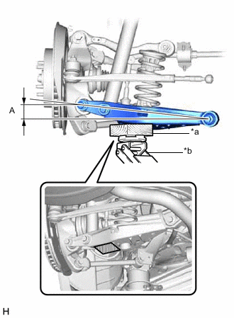
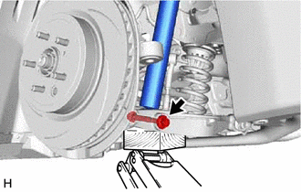
*a Wooden Block *b Jack 
Wooden block placement location Using a jack and wooden block, apply load to the suspension so that the rear No. 2 suspension arm assembly is positioned as shown in the illustration.
CAUTION:
-
Do not raise the jack up too high.
-
The vehicle could fall, resulting in a serious accident.
Note
-
When jacking up the rear No. 2 suspension arm assembly, be sure to jack it up slowly.
-
Make sure to perform this operation with the vehicle kept as low as possible.
Standard Length (A) 18.1 mm (0.713 in.) -
-
-
INSTALL REAR NO. 2 SUSPENSION ARM ASSEMBLY
-
INSTALL REAR SHOCK ABSORBER ASSEMBLY (for Lower Side)
-
Install the rear shock absorber assembly with the bolt.
- Torque:
- 110 N*m { 1122 kgf*cm, 81 ft.*lbf }
Note
Because the nut has its own stopper, do not turn the nut. Tighten the bolt with the nut secured.
-
-
INSTALL REAR NO. 1 SUSPENSION ARM ASSEMBLY
-
INSTALL REAR HEIGHT CONTROL SENSOR SUB-ASSEMBLY
-
INSTALL REAR SUSPENSION ARM COVER
-
INSTALL REAR WHEEL
-
INSTALL LUGGAGE COMPARTMENT TRIM COVER
-
INSPECT AND ADJUST REAR WHEEL ALIGNMENT
-
INITIALIZE HEIGHT CONTROL SENSOR SIGNAL
-
ADJUST HEADLIGHT AIMING