REAR SHOCK ABSORBER REMOVAL
CAUTION / NOTICE / HINT
The necessary procedures (adjustment, calibration, initialization, or registration) that must be performed after parts are removed, installed, or replaced during the rear shock absorber assembly removal/installation are shown below.
| Replacement Part or Procedure | Necessary Procedure | Effect/Inoperative when not Performed | Link |
|---|---|---|---|
| Rear wheel alignment adjustment |
|
|
|
| Removal/installation of rear height control sensor sub-assembly | Perform headlight control computer assembly LH initialization | Headlight leveling function |
Tech Tips
-
Use the same procedure for the RH side and LH side.
-
The following procedure is for the LH side.
PROCEDURE
-
REMOVE LUGGAGE COMPARTMENT TRIM COVER
-
REMOVE REAR WHEEL
-
REMOVE REAR SUSPENSION ARM COVER
-
SEPARATE REAR HEIGHT CONTROL SENSOR SUB-ASSEMBLY
-
SEPARATE REAR STEERING TIE ROD ASSEMBLY
-
SEPARATE REAR NO. 1 SUSPENSION ARM ASSEMBLY
-
REMOVE REAR STABILIZER LINK ASSEMBLY
-
SEPARATE REAR SHOCK ABSORBER ASSEMBLY (for Lower Side)
-
REMOVE REAR COIL SPRING
-
REMOVE REAR UPPER COIL SPRING INSULATOR
-
REMOVE REAR LOWER COIL SPRING INSULATOR
-
REMOVE REAR SHOCK ABSORBER ASSEMBLY (for Upper Side)
-
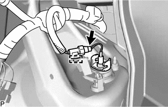
Disconnect the connector.
-
Disengage the wire harnesses clamp from the actuator harness clamp.
-
Disengage the 2 clamps and remove the actuator harness clamp from the vehicle body.
-
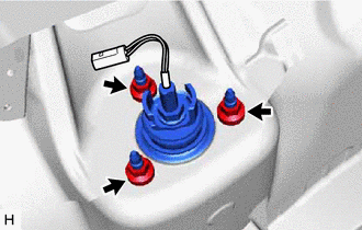
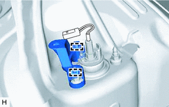
Remove the 3 nuts and rear shock absorber assembly from the vehicle body.
-
-
REMOVE REAR SUSPENSION SUPPORT ASSEMBLY
-
Secure the rear actuator support bracket of the rear shock absorber assembly between aluminum plates in a vise.
Note
Do not overtighten the vise.
-
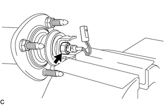
Using a 17 mm deep socket wrench, remove the rear support to rear shock absorber nut and rear actuator support bracket from the rear shock absorber assembly.
Note
-
Do not pinch the wire harness when removing the rear support to rear shock absorber nut with the deep socket wrench.
-
When inserting the wire harness and connector into the deep socket wrench, do not excessively bend the wire harness.
-
-
Remove the rear shock absorber cushion washer, rear No. 1 shock absorber cushion, rear suspension support assembly and rear No. 2 shock absorber cushion from the rear shock absorber assembly.
-
-
REMOVE REAR NO. 1 SPRING BUMPER
-
Remove the rear No. 1 spring bumper from the rear shock absorber assembly.
-