FRONT SUSPENSION MEMBER REMOVAL
CAUTION / NOTICE / HINT
The necessary procedures (adjustment, calibration, initialization, or registration) that must be performed after parts are removed, installed, or replaced during the front suspension crossmember sub-assembly removal/installation are shown below.
| Replacement Part or Procedure | Necessary Procedure | Effect/Inoperative when not Performed | Link |
|---|---|---|---|
| Disconnect cable from negative battery terminal | Memorize steering angle neutral point | Parking assist monitor system | |
| Lane departure alert system (w/ Steering Control) | |||
| Pre-crash safety system | |||
| Adaptive high beam system | |||
| Reset power trunk lid | Power trunk lid system | ||
| Front wheel alignment adjustment |
|
|
Tech Tips
-
Use the same procedure for RHD and LHD vehicles.
-
The procedure listed below is for LHD vehicles.
PROCEDURE
-
REMOVE FRONT SUSPENSION CROSSMEMBER SUB-ASSEMBLY
-
REMOVE FRONT ENGINE MOUNTING INSULATOR
-
REMOVE FRONT STABILIZER BAR
-
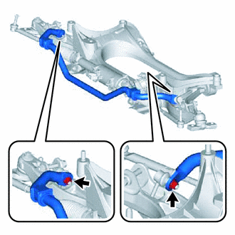
Remove the 2 nuts and front stabilizer bar.
Tech Tips
If the ball joint turns together with the nut, use a 6 mm hexagon wrench to hold the stud bolt.
-
-
SEPARATE FRONT LOWER SUSPENSION ARM ASSEMBLY LH
-
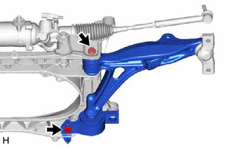
Remove the 2 bolts, 2 nuts, washer and front suspension member mount bracket sub-assembly, and separate the front lower suspension arm assembly LH.
-
-
SEPARATE FRONT LOWER SUSPENSION ARM ASSEMBLY RH
Tech Tips
Perform the same procedure as for the LH side.
-
REMOVE POWER STEERING LINK ASSEMBLY
-
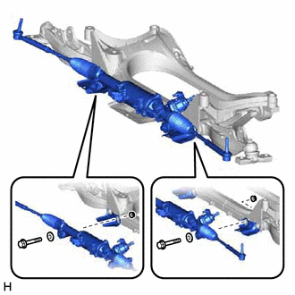
Remove the 2 bolts, 2 nuts, 2 washers, 2 front suspension member brace plates and power steering link assembly from the front suspension crossmember sub-assembly.
Tech Tips
Remove the power steering link assembly together with the front lower suspension arm assembly LH and front lower suspension arm assembly RH.
-