FRONT STABILIZER BAR REMOVAL
CAUTION / NOTICE / HINT
The necessary procedures (adjustment, calibration, initialization, or registration) that must be performed after parts are removed, installed, or replaced during the front stabilizer bar removal/installation are shown below.
| Replacement Part or Procedure | Necessary Procedure | Effect/Inoperative when not Performed | Link |
|---|---|---|---|
| Front wheel alignment adjustment |
|
|
PROCEDURE
-
REMOVE FRONT WHEELS
-
REMOVE NO. 1 ENGINE UNDER COVER ASSEMBLY
-
SEPARATE FRONT FENDER LINER LH
-
SEPARATE FRONT FENDER LINER RH
Tech Tips
Perform the same procedure as for the LH side.
-
REMOVE NO. 1 OIL COOLER BRACKET
-
Remove the bolt, 5 nuts and No. 1 oil cooler bracket.
-
-
REMOVE OIL COOLER BRACKET
-
Remove the bolt, 3 nuts and oil cooler bracket.
-
-
REMOVE NO. 2 FRAME CROSSMEMBER ASSEMBLY
-
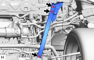
Remove the 3 bolts and No. 2 frame crossmember assembly.
-
-
REMOVE NO. 1 FRAME CROSSMEMBER ASSEMBLY
Tech Tips
Perform the same procedure as for the No. 2 frame crossmember assembly.
-
REMOVE FRONT STABILIZER LINK SUB-ASSEMBLY LH
-
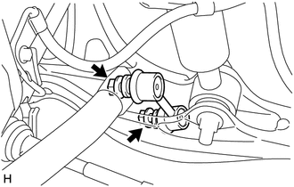
Remove the 2 nuts and front stabilizer link sub-assembly LH from the front stabilizer bar and front lower suspension arm assembly LH.
Tech Tips
If the ball joint turns together with the nut, use a 6 mm hexagon wrench to hold the stud bolt.
-
-
REMOVE FRONT STABILIZER LINK SUB-ASSEMBLY RH
Tech Tips
Perform the same procedure as for the LH side.
-
REMOVE REAR ENGINE UNDER COVER LH
-
REMOVE REAR ENGINE UNDER COVER RH
Tech Tips
Perform the same procedure as for the LH side.
-
REMOVE FRONT NO. 1 STABILIZER BRACKET LH
-
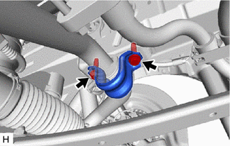
Remove the 2 bolts and front No. 1 stabilizer bracket LH from the front stabilizer bracket LH.
-
-
REMOVE FRONT NO. 1 STABILIZER BRACKET RH
Tech Tips
Perform the same procedure as for the LH side.
-
REMOVE FRONT STABILIZER BAR
-
Remove the front stabilizer bar from the vehicle.
-
-
REMOVE FRONT STABILIZER BAR BUSHING
-
Remove the 2 front stabilizer bar bushings from the front stabilizer bar.
-
-
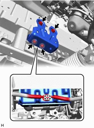
REMOVE FRONT STABILIZER BRACKET LH
-
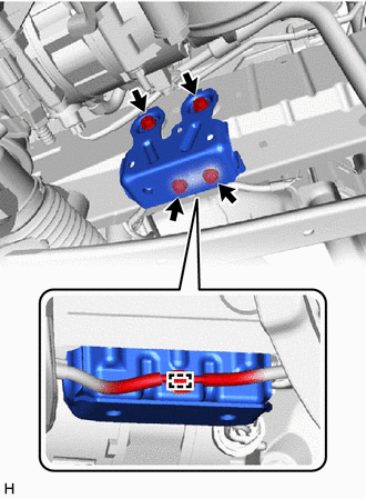
for LHD:
-
Separate the wire harness clamp from the front stabilizer bracket LH.
-
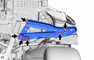
Remove the 4 bolts and front stabilizer bracket LH from the frame.
-
-
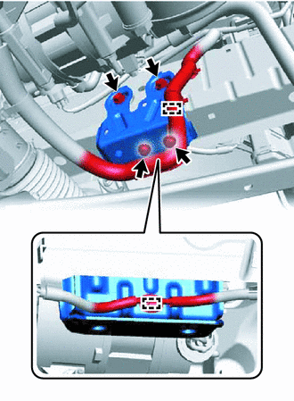
for RHD:
-
Separate the 2 wire harness clamps from the front stabilizer bracket LH.
-
Remove the 4 bolts and front stabilizer bracket LH from the frame.
-
-
-
REMOVE FRONT STABILIZER BRACKET RH
-
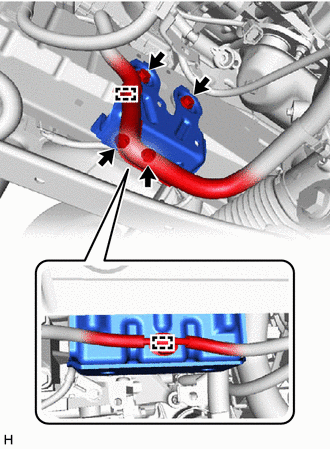
for LHD:
-
Separate the 2 wire harness clamps from the front stabilizer bracket RH.
-
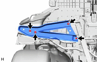
Remove the 4 bolts and front stabilizer bracket RH from the frame.
-
-
for RHD:
-
Separate the wire harness clamp from the front stabilizer bracket RH.
-
Remove the 4 bolts and front stabilizer bracket RH from the frame.
-
-