REAR SUSPENSION MEMBER REMOVAL

CAUTION / NOTICE / HINT
The necessary procedures (adjustment, calibration, initialization, or registration) that must be performed after parts are removed, installed, or replaced during the rear suspension member sub-assembly removal/installation are shown below.
| Replacement Part or Procedure | Necessary Procedure | Effect/Inoperative when not Performed | Link |
|---|---|---|---|
| Removal/installation of rear disc | Parking brake bedding | Electric parking brake system | |
| Rear wheel alignment adjustment |
|
|
|
| Removal/installation of rear height control sensor sub-assembly | Perform headlight control computer assembly LH initialization | Headlight leveling function |
PROCEDURE
-
REMOVE REAR WHEEL
-
REMOVE FRONT CENTER FLOOR COVER LH
-
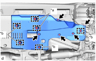
*a Clamp *b Grommet Remove the 5 clips.
-
Disengage the 2 clamps and 4 grommets to remove the front center floor cover LH.
-
-
REMOVE FRONT CENTER FLOOR COVER RH
Tech Tips
Perform the same procedure as for the LH side.
-
REMOVE NO. 1 FLOOR UNDER COVER ASSEMBLY
-
REMOVE FRONT CENTER FLOOR BRACE
-
Remove the 6 bolts and 2 nuts.
-
Disengage the 2 clamps to remove the front center floor brace.
-
-
REMOVE PROPELLER SHAFT WITH CENTER BEARING ASSEMBLY
-
DISCONNECT TAIL EXHAUST PIPE LH
-
DISCONNECT TAIL EXHAUST PIPE ASSEMBLY
-
REMOVE REAR SUSPENSION ARM COVER LH
-
REMOVE REAR SUSPENSION ARM COVER RH
Tech Tips
Perform the same procedure as for the LH side.
-
REMOVE REAR HEIGHT CONTROL SENSOR SUB-ASSEMBLY
-
REMOVE REAR AXLE SHAFT NUT LH
-
REMOVE REAR AXLE SHAFT NUT RH
Tech Tips
Perform the same procedure as for the LH side.
-
SEPARATE REAR DISC BRAKE CALIPER ASSEMBLY LH
-
SEPARATE REAR DISC BRAKE CALIPER ASSEMBLY RH
Tech Tips
Perform the same procedure as for the LH side.
-
REMOVE PARKING BRAKE SHOE ADJUSTING HOLE PLUG
-
Remove the 2 parking brake shoe adjusting hole plugs.
-
-
REMOVE REAR DISC LH
-
REMOVE REAR DISC RH
Tech Tips
Perform the same procedure as for the LH side.
-
REMOVE PARKING BRAKE ASSEMBLY (for LH Side)
-
REMOVE PARKING BRAKE ASSEMBLY (for RH Side)
Tech Tips
Perform the same procedure as for the LH side.
-
SEPARATE REAR SPEED SENSOR LH
-
SEPARATE REAR SPEED SENSOR RH
Tech Tips
Perform the same procedure as for the LH side.
-
SEPARATE NO. 2 PARKING BRAKE CABLE ASSEMBLY
-
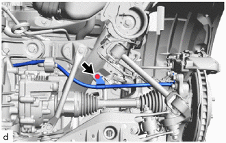
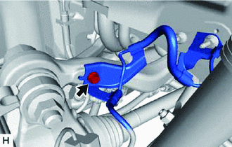
Remove the bolt to separate the No. 2 parking brake cable assembly from the rear suspension member sub-assembly.
-
-
SEPARATE NO. 3 PARKING BRAKE CABLE ASSEMBLY
Tech Tips
Perform the same procedure as for the No. 2 parking brake cable assembly.
-
SEPARATE REAR STEERING TIE ROD ASSEMBLY LH
-
SEPARATE REAR STEERING TIE ROD ASSEMBLY RH
Tech Tips
Perform the same procedure as for the LH side.
-
REMOVE REAR NO. 1 SUSPENSION ARM ASSEMBLY LH
-
REMOVE REAR NO. 1 SUSPENSION ARM ASSEMBLY RH
Tech Tips
Perform the same procedure as for the LH side.
-
REMOVE REAR STABILIZER LINK ASSEMBLY LH
-
REMOVE REAR STABILIZER LINK ASSEMBLY RH
Tech Tips
Perform the same procedure as for the LH side.
-
SEPARATE REAR SHOCK ABSORBER ASSEMBLY LH
-
SEPARATE REAR SHOCK ABSORBER ASSEMBLY RH
Tech Tips
Perform the same procedure as for the LH side.
-
REMOVE REAR SUSPENSION MEMBER BRACE LH
-
REMOVE REAR SUSPENSION MEMBER BRACE RH
Tech Tips
Perform the same procedure as for the LH side.
-
REMOVE REAR COIL SPRING LH
-
REMOVE REAR COIL SPRING RH
Tech Tips
Perform the same procedure as for the LH side.
-
REMOVE REAR UPPER COIL SPRING INSULATOR LH
-
REMOVE REAR UPPER COIL SPRING INSULATOR RH
Tech Tips
Perform the same procedure as for the LH side.
-
REMOVE REAR LOWER COIL SPRING INSULATOR LH
-
REMOVE REAR LOWER COIL SPRING INSULATOR RH
Tech Tips
Perform the same procedure as for the LH side.
-
REMOVE REAR NO. 2 SUSPENSION ARM ASSEMBLY LH
-
REMOVE REAR NO. 2 SUSPENSION ARM ASSEMBLY RH
Tech Tips
Perform the same procedure as for the LH side.
-
SEPARATE REAR NO. 1 UPPER CONTROL ARM ASSEMBLY LH
-
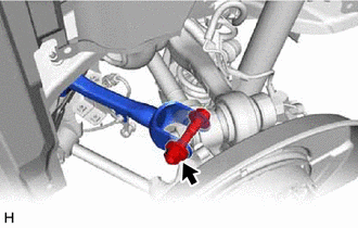
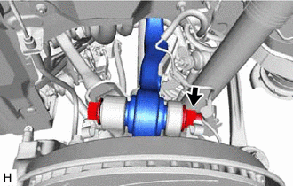
Remove the bolt, nut and washer and separate the rear No. 1 upper control arm assembly LH from the rear axle assembly.
Note
Because the bolt has its own stopper, do not turn the bolt. Loosen the nut with the bolt secured.
-
-
SEPARATE REAR NO. 1 UPPER CONTROL ARM ASSEMBLY RH
Tech Tips
Perform the same procedure as for the LH side.
-
LOOSEN REAR NO. 2 UPPER CONTROL ARM ASSEMBLY LH
-
Remove the bolt and separate the rear speed sensor LH from the rear No. 2 upper control arm assembly LH.
-
Loosen the rear No. 2 upper control arm assembly LH nut (rear axle assembly side).
Note
-
Do not remove the bolt and nut.
-
Because the bolt has its own stopper, do not turn the bolt. Loosen the nut with the bolt secured.
-
-
-
LOOSEN REAR NO. 2 UPPER CONTROL ARM ASSEMBLY RH
Tech Tips
Perform the same procedure as for the LH side.
-
REMOVE REAR AXLE ASSEMBLY LH
-
REMOVE REAR AXLE ASSEMBLY RH
Tech Tips
Perform the same procedure as for the LH side.
-
REMOVE REAR DRIVE SHAFT ASSEMBLY LH
-
REMOVE REAR DRIVE SHAFT ASSEMBLY RH
Tech Tips
Use the same procedure as for the LH side.
-
REMOVE REAR BODY MOUNTING CUSHION SUB-ASSEMBLY LH
-
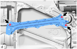
Remove the 3 bolts and rear body mounting cushion sub-assembly LH.
-
-
REMOVE REAR BODY MOUNTING CUSHION SUB-ASSEMBLY RH
Tech Tips
Perform the same procedure as for the LH side.
-
DISCONNECT NO. 4 FLOOR WIRE
-
REMOVE REAR SUSPENSION MEMBER SUB-ASSEMBLY
-
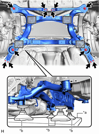
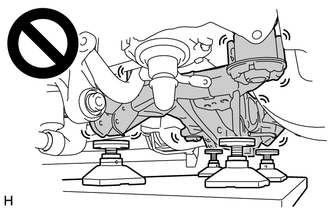
*a Engine Lifter *b Attachment 
Attachment placement location Support the rear suspension member sub-assembly with an engine lifter using 4 attachments or equivalent tools as shown in the illustration.
CAUTION:
-
The rear suspension member sub-assembly is a very heavy component. Make sure that it is supported securely.
-
If the rear suspension member sub-assembly is not securely supported, it may drop, resulting in serious injury.
Note
-
Use attachments to keep the rear suspension member sub-assembly level.
-
The rear suspension member sub-assembly is a heavy component. Make sure that it is supported securely.
-
-
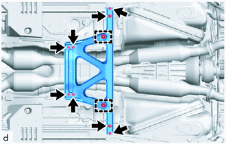
Remove the 8 bolts, 4 nuts, rear floor panel brace sub-assembly LH, rear floor panel brace sub-assembly RH, rear suspension member lower stopper sub-assembly LH and rear suspension member lower stopper sub-assembly RH.
-
Slowly lower the rear suspension member sub-assembly.
Note
When lowering the rear suspension member sub-assembly, be careful not to damage the vehicle body or other components installed to the vehicle.
-
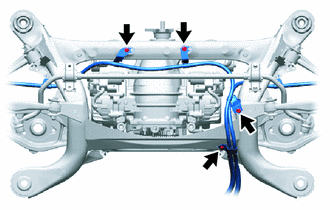
Remove the 4 bolts to separate the No. 2 parking brake cable assembly and No. 3 parking brake cable assembly from the rear suspension member sub-assembly.
-
-
REMOVE NO. 4 FLOOR WIRE
-
REMOVE REAR SUSPENSION ARM BRACKET ASSEMBLY
-
REMOVE TORQUE VECTORING DIFFERENTIAL FDU (FINAL DRIVE UNIT)
-
REMOVE REAR STABILIZER BAR SUB-ASSEMBLY
-
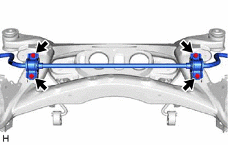
Remove the 4 bolts and rear stabilizer bar sub-assembly with 2 rear No. 1 stabilizer bar brackets from the rear suspension member sub-assembly.
-
-
REMOVE REAR NO. 1 UPPER CONTROL ARM ASSEMBLY LH
-
REMOVE REAR NO. 1 UPPER CONTROL ARM ASSEMBLY RH
Tech Tips
Perform the same procedure as for the LH side.
-
REMOVE REAR NO. 2 UPPER CONTROL ARM ASSEMBLY LH
-
REMOVE REAR NO. 2 UPPER CONTROL ARM ASSEMBLY RH
Tech Tips
Perform the same procedure as for the LH side.
-
REMOVE REAR NO. 1 DIFFERENTIAL MOUNT CUSHION
-
REMOVE REAR NO. 2 DIFFERENTIAL MOUNT CUSHION
-
REMOVE REAR SUSPENSION MEMBER REAR LOWER STOPPER (for LH Side)
-
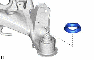
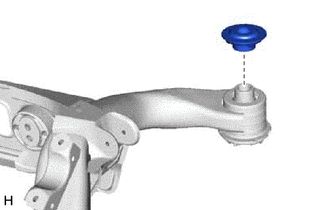
Remove the rear suspension member rear lower stopper from the rear suspension member sub-assembly.
-
-
REMOVE REAR SUSPENSION MEMBER REAR LOWER STOPPER (for RH Side)
Tech Tips
Perform the same procedure as for the LH side.
-
REMOVE REAR SUSPENSION MEMBER REAR UPPER STOPPER (for LH Side)
-
Remove the rear suspension member rear upper stopper from the rear suspension member sub-assembly.
-
-
REMOVE REAR SUSPENSION MEMBER REAR UPPER STOPPER (for RH Side)
Tech Tips
Perform the same procedure as for the LH side.
-
REMOVE REAR SUSPENSION MEMBER FRONT BODY MOUNTING CUSHION (for LH Side)
-
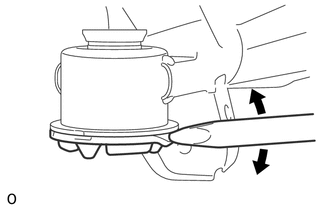
Using a chisel and hammer, bend the rear suspension member front body mounting cushion rib.
-
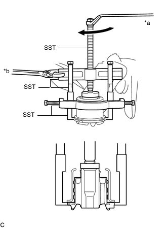
*a Turn *b Hold Using SST, remove the rear suspension member front body mounting cushion while applying grease into the clearance between the rear suspension member front body mounting cushion and the rear suspension member sub-assembly.
- SST
- 09950-40011 ( 09951-04020, 09952-04010, 09953-04030, 09954-04010, 09955-04051, 09957-04010, 09958-04011 )
- 09950-60010 ( 09951-00410 )
Note
-
Apply grease to the threads and tip of the SST center bolt before use.
-
Be careful as the rear suspension member front body mounting cushion may fly out.
-
The rear suspension member front body mounting cushion cannot be reused.
-
-
REMOVE REAR SUSPENSION MEMBER FRONT BODY MOUNTING CUSHION (for RH Side)
Tech Tips
Perform the same procedure as for the LH side.
-
REMOVE REAR SUSPENSION MEMBER REAR BODY MOUNTING CUSHION (for LH Side)
-
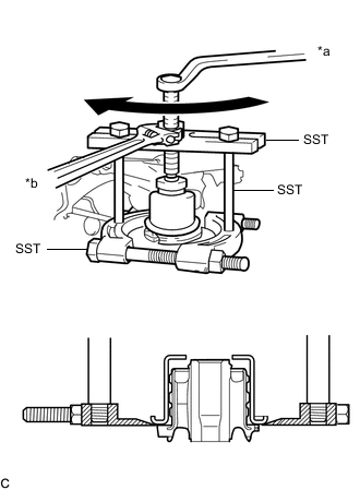
*a Turn *b Hold Using SST, remove the rear suspension member rear body mounting cushion while applying grease into the clearance between the rear suspension member rear body mounting cushion and the rear suspension member sub-assembly.
- SST
- 09950-00020
- 09950-00030
- 09950-40011 ( 09957-04010 )
- 09950-60010 ( 09951-00390 )
Note
-
Apply grease to the threads and tip of the SST center bolt before use.
-
Be careful as the rear suspension member rear body mounting cushion may fly out.
-
The rear suspension member rear body mounting cushion cannot be reused.
-
-
REMOVE REAR SUSPENSION MEMBER REAR BODY MOUNTING CUSHION (for RH Side)
Tech Tips
Perform the same procedure as for the LH side.