REAR STABILIZER BAR REMOVAL
CAUTION / NOTICE / HINT
The necessary procedures (adjustment, calibration, initialization, or registration) that must be performed after parts are removed, installed, or replaced during the rear stabilizer bar sub-assembly removal/installation are shown below.
| Replacement Part or Procedure | Necessary Procedure | Effect/Inoperative when not Performed | Link |
|---|---|---|---|
| Removal/installation of rear disc | Parking brake bedding | Electric parking brake system | |
| Rear wheel alignment adjustment |
|
|
|
| Removal/installation of rear height control sensor sub-assembly | Perform headlight control computer assembly LH initialization | Headlight leveling function |
PROCEDURE
-
REMOVE REAR WHEEL
-
REMOVE REAR STABILIZER LINK ASSEMBLY LH
-
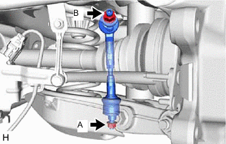
Remove the nut (A).
-
Remove the nut (B) and rear stabilizer link assembly LH.
Tech Tips
If the ball joint turns together with the nut, use a 6 mm hexagon socket wrench to hold the stud bolt.
-
-
REMOVE REAR STABILIZER LINK ASSEMBLY RH
Tech Tips
Perform the same procedure as for the LH side.
-
REMOVE REAR SUSPENSION MEMBER SUB-ASSEMBLY
-
REMOVE REAR STABILIZER BAR SUB-ASSEMBLY
-
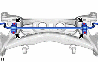
Remove the 4 bolts, rear stabilizer bar sub-assembly and 2 rear No. 1 stabilizer bar brackets from the rear suspension member sub-assembly.
-
Remove the 2 rear No. 1 stabilizer bar brackets from the 2 rear stabilizer bushings.
-
Remove the 2 rear stabilizer bushings from the rear stabilizer bar.
-