REAR WHEEL ALIGNMENT ADJUSTMENT
CAUTION / NOTICE / HINT
The necessary procedures (adjustment, calibration, initialization, or registration) that must be performed after parts are removed, installed, or replaced when performing the rear wheel alignment are shown below.
| Replacement Part or Procedure | Necessary Procedure | Effect/Inoperative when not Performed | Link |
|---|---|---|---|
| Rear wheel alignment adjustment |
|
|
PROCEDURE
-
INSPECT TIRES
-
MEASURE VEHICLE HEIGHT
-
INSPECT CAMBER
Note
Inspect while the vehicle is unloaded.
-
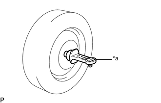
*a Camber-caster-kingpin Gauge Install a camber-caster-kingpin gauge.
-
Inspect the camber.
Camber (Unloaded Vehicle) Camber Inclination Right-left Difference -1°16' +/- 0°45' (-1.27° +/- 0.75°) 0°45' (0.75°) or less Tech Tips
Camber is not adjustable. If the measurement is not within the specified range, inspect the suspension parts for damage and/or wear, and replace them if necessary.
-
-
INSPECT TOE-IN
Note
Inspect while the vehicle is unloaded.
-
Bounce the vehicle up and down at the corners to stabilize the suspension.
-
Release the parking brake and move the shift lever to N.
-
Push the vehicle straight ahead approximately 5 m (16.4 ft.). (Step A)
-
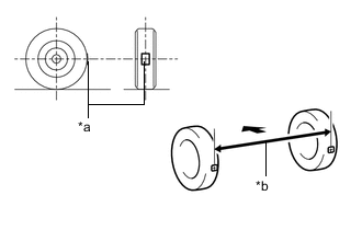
*a Tread Center Mark *b Dimension B 
Front of the Vehicle Put tread center marks on the rearmost points of the rear wheels and measure the distance between the marks (dimension B).
-
Slowly push the vehicle straight ahead to cause the rear wheels to rotate 180°. Use the rear tire valve as a reference point.
Tech Tips
Do not allow the wheels to rotate more than 180°. If the wheels rotate more than 180°, perform the procedure from step A again.
-
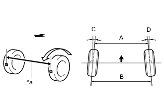
*a Dimension A Front of the Vehicle Measure the distance between the tread center marks on the front of the rear wheels (dimension A).
Toe-in (Unloaded Vehicle) Specified Condition C + D: 0°15' +/- 0°10' (0.25° +/- 0.17°) B - A: 3.0 +/- 2.0 mm (0.118 +/- 0.0787 in.) Tech Tips
Measure "B - A" only when "C + D" cannot be measured.
If the toe-in is not within the specified range, adjust it at the steering rack ends.
-
-
ADJUST TOE-IN
-
Measure the thread lengths of the right and left steering rack ends.
Standard Difference 1.5 mm (0.0591 in.) or less -
Remove the rear steering rack boot clips.
-
Loosen the rear steering tie rod assembly lock nuts.
-
Adjust the steering rack ends if the difference in thread length between the right and left steering rack ends is not within the specified range.
-
If the toe-in measurement is greater than the specified range (too much toe-out), extend the shorter steering rack end so that the difference in length is within the specified range.
-
If the toe-in measurement is less than the specified range (too much toe-in), shorten the longer steering rack end so that the difference in length is within the specified range.
-
Measure the toe-in.
-
-
Turn the right and left steering rack ends by an equal amount to adjust the toe-in.
Toe-in (Unloaded Vehicle) Specified Condition C + D: 0°15' +/- 0°10' (0.25° +/- 0.17°) B - A: 3.0 +/- 2.0 mm (0.118 +/- 0.0787 in.) Tech Tips
Perform adjustments so that the value is as close as possible to the median of the specified range.
-
Tighten the rear steering tie rod assembly lock nuts.
- Torque:
- 55 N*m { 561 kgf*cm, 41 ft.*lbf }
-
Place the rear steering rack boots on the seats and install the rear steering rack boot clips.
-
-
INSPECT REAR SUSPENSION
-
Inspect the rear suspension member sub-assembly.
-
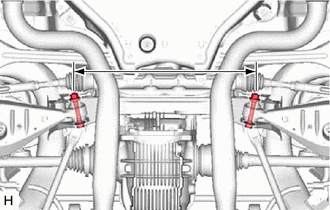
Measure the distance between the centers of the 2 installation bolts of the rear No. 2 suspension arm assembly LH and RH.
Standard 496.5 to 503.5 mm (1.63 to 1.65 ft.) If the distance is not as specified, replace the rear suspension member sub-assembly.
Tech Tips
Refer to the instructions for removal and installation of the rear suspension member sub-assembly.
-
-
Inspect the rear No. 2 suspension arm assembly.
-
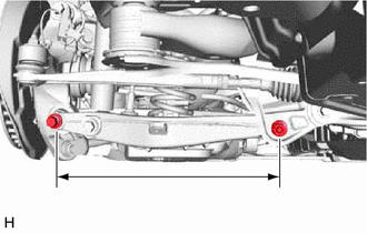
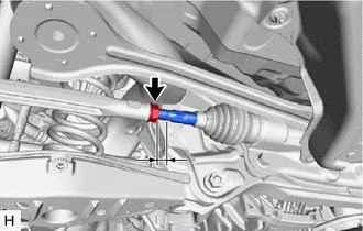
Measure the distance between the centers of the 2 installation bolts of the rear No. 2 suspension arm assembly.
Standard 443.6 to 444.6 mm (1.456 to 1.458 ft.) If the distance is not as specified, replace the rear No. 2 suspension arm assembly.
Tech Tips
Refer to the instructions for removal and installation of the rear No. 2 suspension arm assembly.
-
-
Inspect the rear No. 2 upper control arm assembly.
-
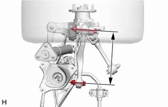
Measure the distance between the centers of the 2 installation bolts of the rear No. 2 upper control arm assembly.
Standard 298.5 to 299.5 mm (11.76 to 11.79 in.) If the distance is not as specified, replace the rear No. 2 upper control arm assembly.
Tech Tips
Refer to the instructions for removal and installation of the rear No. 2 upper control arm assembly.
-
-
-
ALIGN FRONT WHEELS FACING STRAIGHT AHEAD
-
PERFORM YAW RATE AND ACCELERATION SENSOR AND ROLL RATE AND VERTICAL ACCELERATION SENSOR ZERO POINT CALIBRATION