FRONT LOWER SUSPENSION ARM REMOVAL
CAUTION / NOTICE / HINT
The necessary procedures (adjustment, calibration, initialization, or registration) that must be performed after parts are removed, installed, or replaced during the front lower suspension arm assembly removal/installation are shown below.
| Replacement Part or Procedure | Necessary Procedure | Effect/Inoperative when not Performed | Link |
|---|---|---|---|
| Front wheel alignment adjustment |
|
|
Tech Tips
-
Use the same procedure for the RH side and LH side.
-
The following procedure is for the LH side.
PROCEDURE
-
REMOVE FRONT WHEEL
-
REMOVE NO. 1 ENGINE UNDER COVER ASSEMBLY
-
REMOVE FRONT SUSPENSION MEMBER BRACE SUB-ASSEMBLY
-
SEPARATE FRONT SKID CONTROL SENSOR WIRE
-
SEPARATE FRONT SHOCK ABSORBER WITH COIL SPRING
-
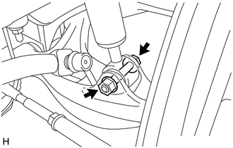
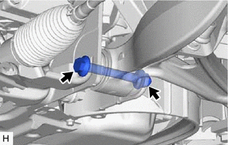
Remove the bolt and nut, and separate the front shock absorber with coil spring from the front lower suspension arm assembly.
Note
Because the nut has its own stopper, do not turn the nut. Loosen the bolt with the nut secured.
-
-
REMOVE FRONT STABILIZER LINK SUB-ASSEMBLY
-
SEPARATE TIE ROD ASSEMBLY
-
SEPARATE FRONT LOWER BALL JOINT ASSEMBLY
-
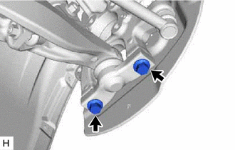
Remove the 2 bolts and separate the front lower ball joint assembly from the steering knuckle.
-
-
REMOVE FRONT LOWER SUSPENSION ARM ASSEMBLY
-
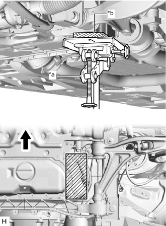
*a Jack *b Wooden Block 
Front of the Vehicle 
Wooden block placement location Using a jack and wooden block, support the front suspension crossmember sub-assembly.
Note
Keep the front suspension crossmember sub-assembly supported until installation of the front lower suspension arm assembly is complete.
-
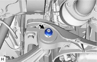
Loosen the installation nut of the lower No. 2 arm bracket sub-assembly.
Note
Do not remove the nut.
-
Remove the bolt, nut and washer on the front of the front lower suspension arm assembly.
-
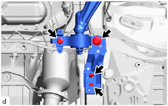
Remove the 4 bolts, nut, strut bar bracket reinforcement, front suspension member mount bracket sub-assembly and front lower suspension arm assembly.
-
-
REMOVE FRONT LOWER BALL JOINT ASSEMBLY
-
REMOVE LOWER NO. 2 ARM BRACKET SUB-ASSEMBLY
-
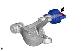
Remove the nut, washer and lower No. 2 arm bracket sub-assembly from the front lower suspension arm assembly.
-