FRONT LOWER BALL JOINT REMOVAL

CAUTION / NOTICE / HINT
The necessary procedures (adjustment, calibration, initialization, or registration) that must be performed after parts are removed, installed, or replaced during the front lower ball joint assembly removal/installation are shown below.
| Replacement Part or Procedure | Necessary Procedure | Effect/Inoperative when not Performed | Link |
|---|---|---|---|
| Front wheel alignment adjustment |
|
|
Tech Tips
-
Use the same procedure for the RH side and LH side.
-
The following procedure is for the LH side.
PROCEDURE
-
REMOVE FRONT LOWER SUSPENSION ARM ASSEMBLY
-
REMOVE FRONT LOWER BALL JOINT ASSEMBLY
-
Secure the front lower suspension arm assembly in a vise using aluminum plates.
Note
When using a vise, do not overtighten it.
-
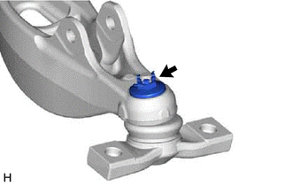
Remove the clip and nut.
-
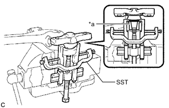
*a Spacer Using SST, remove the front lower ball joint assembly from the front lower suspension arm assembly as shown in the illustration.
- SST
- 09950-40011 ( 09951-04010, 09952-04010, 09953-04020, 09954-04010, 09955-04051, 09957-04010, 09958-04011 )
Note
-
Do not damage the front lower ball joint dust cover.
-
Do not damage the front lower suspension arm assembly.
-
Make sure that SST is securely positioned on the spacer.
Tech Tips
If the front lower suspension arm assembly spacer has come off, replace the front lower suspension arm assembly with a new one.
-