DIFFERENTIAL MOUNT CUSHION REMOVAL

CAUTION / NOTICE / HINT
The necessary procedures (adjustment, calibration, initialization, or registration) that must be performed after parts are removed, installed, or replaced during the rear No. 1 differential mount cushion or rear No. 2 differential mount cushion removal/installation are shown below.
| Replacement Part or Procedure | Necessary Procedure | Effect/Inoperative when not Performed | Link |
|---|---|---|---|
| Disconnect cable from negative battery terminal | Memorize steering angle neutral point | Parking assist monitor system | |
| Lane departure alert system (w/ Steering Control) | |||
| Pre-crash safety system | |||
| Adaptive high beam system | |||
| Reset power trunk lid | Power trunk lid system | ||
| Removal/installation of rear disc | Parking brake bedding | Electric parking brake system | |
| Rear wheel alignment adjustment |
|
|
|
| Removal/installation of rear height control sensor sub-assembly | Perform headlight control computer assembly LH initialization | Headlight leveling function |
PROCEDURE
-
REMOVE TORQUE VECTORING DIFFERENTIAL FDU (FINAL DRIVE UNIT)
-
REMOVE REAR NO. 1 DIFFERENTIAL MOUNT CUSHION
-
Using SST, remove the rear No. 1 differential mount cushion.
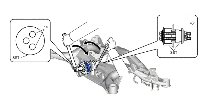
*a SST bolt location - - 
Front of the Vehicle - - - SST
- 09527-17011
- 09570-24011
Note
-
Before using SST, apply grease to the SST bolts.
-
Be sure to use the correct combination of SST.
-
Make sure that SST (09527-17011) contacts the entire circumference of the rear No. 1 differential mount cushion.
-
Do not tilt the bolts of SST.
-
Tighten the 2 bolts of SST so that they enter the 2 holes of the rear No. 1 differential mount cushion by an equal amount.
-
Do not bring SST (09527-17011) into contact with the rear suspension member sub-assembly.
Tech Tips
Install the 2 SST bolts to the 2 SST holes as shown in the illustration.
-
-
REMOVE REAR NO. 2 DIFFERENTIAL MOUNT CUSHION
-
Using SST, remove the rear No. 2 differential mount cushion.
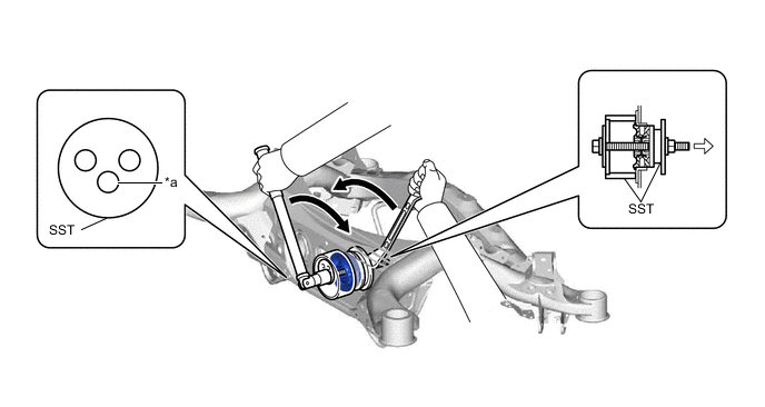
*a SST bolt location - - Front of the Vehicle - - - SST
- 09316-12010
- 09570-24011
Note
-
Before using SST, apply grease to the SST bolt.
-
Be sure to use the correct combination of SST.
-
Make sure that SST (09316-12010) contacts the entire circumference of the rear No. 2 differential mount cushion.
-
Do not tilt the bolt of SST.
-
Do not bring SST (09316-12010) into contact with the rear suspension member sub-assembly.
Tech Tips
Install the SST bolt to the SST hole as shown in the illustration.
-