TORQUE VECTORING DIFFERENTIAL ECU REMOVAL
CAUTION / NOTICE / HINT
The necessary procedures (adjustment, calibration, initialization, or registration) that must be performed after parts are removed, installed, or replaced during the torque vectoring differential ECU assembly removal/installation are shown below.
| Replacement Part or Procedure | Necessary Procedure | Effect/Inoperative when not Performed | Link |
|---|---|---|---|
| Disconnect cable from negative battery terminal | Memorize steering angle neutral point | Parking assist monitor system | |
| Lane departure alert system (w/ Steering Control) | |||
| Pre-crash safety system | |||
| Adaptive high beam system | |||
| Reset power trunk lid | Power trunk lid system | ||
| Replacement of torque vectoring differential ECU assembly | All learning | Torque vectoring differential system |
PROCEDURE
-
PRECAUTION
Note
After turning the engine switch off, waiting time may be required before disconnecting the cable from the negative (-) battery terminal. Therefore, make sure to read the disconnecting the cable from the negative (-) battery terminal notices before proceeding with work.
-
DISCONNECT CABLE FROM NEGATIVE BATTERY TERMINAL
Note
When disconnecting the cable, some systems need to be initialized after the cable is reconnected.
-
REMOVE LUGGAGE COMPARTMENT FLOOR MAT (w/o Spare Tire)
-
REMOVE LUGGAGE COMPARTMENT FLOOR MAT (w/ Spare Tire)
-
REMOVE LUGGAGE COMPARTMENT TRIM BOX (w/o Spare Tire)
-
REMOVE SPARE WHEEL COVER TRAY (w/o Spare Tire)
-
REMOVE SPARE WHEEL COVER TRAY (w/ Spare Tire)
-
REMOVE SPARE TIRE (w/ Spare Tire)
-
REMOVE ECU BRACKET (w/ Spare Tire)
-
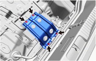
Remove the 4 bolts and ECU bracket.
-
-
REMOVE TORQUE VECTORING DIFFERENTIAL ECU ASSEMBLY
-
Disconnect the 3 connectors (A).
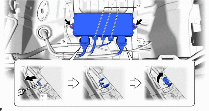
*a Connector (A) *b Connector (B) *c Lock - - -
Using a screwdriver, release the 2 locks and disconnect the 2 connectors (B) as shown in the illustration.
Tech Tips
When disconnecting the connector with lock lever, pull out the lock of the lock lever, disengage the claw and turn the lock lever to disconnect the connector as shown in the illustration.
-
Remove the 2 nuts and torque vectoring differential ECU assembly.
-