TORQUE VECTORING DIFFERENTIAL SYSTEM, Diagnostic DTC:C2A06, C2A07
| DTC Code | DTC Name |
|---|---|
| C2A06 | RH Resolver Circuit |
| C2A07 | LH Resolver Circuit |
DESCRIPTION
The TVD motor contains a TVD motor resolver sensor used to determine the position of the magnetic poles. It is necessary to know the position of the magnetic poles in order to precisely control the TVD motor.
The TVD motor resolver contains a stator equipped with 2 detection coils (S and C) and an excitation coil. When the elliptical shaped rotor turns, the gap between the stator and elliptical shaped rotor changes.
A fixed frequency AC current is sent though the excitation coil. The detection coils (S and C) output an AC waveform with a magnitude relative to the angle of the sensor rotor.
The TVD motor resolver detects the absolute position of the elliptical shaped rotor using the phase and amplitude of the waveform of the detection coils (S and C). Using the information provided by the TVD motor resolver, the ECU calculates the angle and rotational speed of the TVD motor.
The torque vectoring differential ECU assembly monitors the output signal of the TVD motor resolver to detect any malfunctions.
| DTC No. | Detection Item | DTC Detection Condition | Trouble Area | Warning Indicate |
|---|---|---|---|---|
| C2A06 | RH Resolver Circuit | Diagnosis Condition:
Abnormal condition:
Malfunction Time:
Trip logic:
|
|
|
| C2A07 | LH Resolver Circuit | Diagnosis Condition:
Abnormal condition:
Malfunction Time:
Trip logic:
|
|
|
| Vehicle Condition | |||
|---|---|---|---|
| Pattern 1 | Pattern 2 | ||
| Diagnosis Condition | IG power source voltage is 10 V and more | ○ | - |
| PIG power source voltage is 10 V or more | - | ○ | |
| Malfunction Status | Abnormal TVD motor resolver (RH side) control signal | ○ | ○ |
| Detection Time | 0.06 seconds or more | 0.06 seconds or more | |
| Number of Trips | 1 trip | 1 trip | |
Tech Tips
DTC will be output when conditions for either of the patterns in the table above are met.
| Vehicle Condition | |||
|---|---|---|---|
| Pattern 1 | Pattern 2 | ||
| Diagnosis Condition | IG power source voltage is 10 V and more | ○ | - |
| PIG power source voltage is 10 V or more | - | ○ | |
| Malfunction Status | Abnormal TVD motor resolver (LH side) control signal | ○ | ○ |
| Detection Time | 0.06 seconds or more | 0.06 seconds or more | |
| Number of Trips | 1 trip | 1 trip | |
Tech Tips
DTC will be output when conditions for either of the patterns in the table above are met.
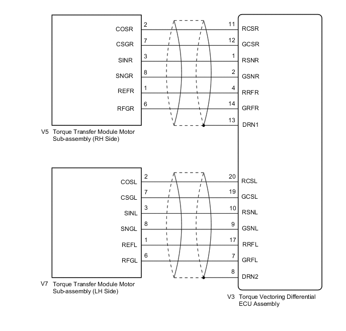
WIRING DIAGRAM
CAUTION / NOTICE / HINT
Tech Tips
-
If the torque vectoring differential ECU assembly has been replaced, perform "All Learning".
-
If the torque transfer module motor sub-assembly has been replaced or removed and installed, perform "Motor Exchange Learning".
PROCEDURE
-
CHECK DTC OUTPUT (TVD)
-
Connect the GTS to the DLC3.
-
Turn the engine switch on (IG).
-
Enter the following menus: Chassis / TVD / Trouble Codes.
-
Check for DTCs.
Chassis > TVD > Trouble CodesResult Result Proceed to DTC C2A06 is output. A DTC C2A07 is output. B -
Turn the engine switch off.
B 
CHECK TORQUE VECTORING DIFFERENTIAL ECU ASSEMBLY (MOTOR RESOLVER CIRCUIT (LH SIDE)) Click here
A 
-
-
CHECK TORQUE VECTORING DIFFERENTIAL ECU ASSEMBLY (MOTOR RESOLVER CIRCUIT (RH SIDE))
-
Disconnect the torque vectoring differential ECU assembly connector.
-
Turn the engine switch on (IG).
-
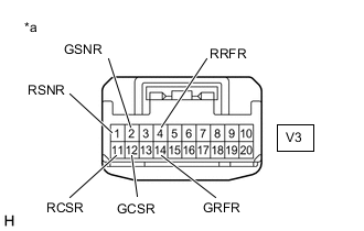
*a Front view of wire harness connector
(to Torque Vectoring Differential ECU Assembly)
Measure the voltage according to the value(s) in the table below.
Standard Voltage Tester Connection Switch Condition Specified Condition V3-4 (RRFR) - Body ground Engine switch on (IG) Below 1 V V3-14 (GRFR) - Body ground Engine switch on (IG) Below 1 V V3-11 (RCSR) - Body ground Engine switch on (IG) Below 1 V V3-12 (GCSR) - Body ground Engine switch on (IG) Below 1 V V3-1 (RSNR) - Body ground Engine switch on (IG) Below 1 V V3-2 (GSNR) - Body ground Engine switch on (IG) Below 1 V Note
Turning the engine switch on (IG) with the torque vectoring differential ECU assembly disconnected causes other DTCs to be stored. Clear the DTCs after performing this inspection.
-
Turn the engine switch off.
-
Measure the resistance according to the value(s) in the table below.
Standard Resistance (Check for Open) Tester Connection Condition Specified Condition V3-4 (RRFR) - V3-14 (GRFR) Always 10 to 12 Ω V3-11 (RCSR) - V3-12 (GCSR) Always 20 to 25 Ω V3-1 (RSNR) - V3-2 (GSNR) Always 19 to 23 Ω Standard Resistance (Check for Short) Tester Connection Condition Specified Condition V3-4 (RRFR) or V3-14 (GRFR) - Body ground and other terminals Always 10 kΩ or higher V3-11 (RCSR) or V3-12 (GCSR) - Body ground and other terminals Always 10 kΩ or higher V3-1 (RSNR) or V3-2 (GSNR) - Body ground and other terminals Always 10 kΩ or higher -
Reconnect the torque vectoring differential ECU assembly connector.
Result Proceed to OK NG
OK 
REPLACE TORQUE VECTORING DIFFERENTIAL ECU ASSEMBLY Click here
NG
-
-
CHECK HARNESS AND CONNECTOR (TORQUE VECTORING DIFFERENTIAL ECU ASSEMBLY - TORQUE TRANSFER MODULE MOTOR SUB-ASSEMBLY (RH SIDE))
-
Disconnect the torque vectoring differential ECU assembly connector.
-
Remove the torque vectoring differential FDU (Final Drive Unit).
-
Disconnect the V5 torque transfer module motor sub-assembly (RH side) connector.
-
Turn the engine switch on (IG).
-
*a Front view of wire harness connector
(to Torque Vectoring Differential ECU Assembly)
Measure the voltage according to the value(s) in the table below.
Standard Voltage Tester Connection Switch Condition Specified Condition V3-4 (RRFR) - Body ground Engine switch on (IG) Below 1 V V3-14 (GRFR) - Body ground Engine switch on (IG) Below 1 V V3-11 (RCSR) - Body ground Engine switch on (IG) Below 1 V V3-12 (GCSR) - Body ground Engine switch on (IG) Below 1 V V3-1 (RSNR) - Body ground Engine switch on (IG) Below 1 V V3-2 (GSNR) - Body ground Engine switch on (IG) Below 1 V Note
Turning the engine switch on (IG) with the torque vectoring differential ECU assembly disconnected causes other DTCs to be stored. Clear the DTCs after performing this inspection.
-
Turn the engine switch off.
-
Measure the resistance according to the value(s) in the table below.
Standard Resistance (Check for Open) Tester Connection Condition Specified Condition V3-4 (RRFR) - V5-1 (REFR) Always Below 1 Ω V3-14 (GRFR) - V5-6 (RFGR) Always Below 1 Ω V3-11 (RCSR) - V5-2 (COSR) Always Below 1 Ω V3-12 (GCSR) - V5-7 (CSGR) Always Below 1 Ω V3-1 (RSNR) - V5-3 (SINR) Always Below 1 Ω V3-2 (GSNR) - V5-8 (SNGR) Always Below 1 Ω Standard Resistance (Check for Short) Tester Connection Condition Specified Condition V3-4 (RRFR) or V5-1 (REFR) - Body ground and other terminals Always 10 kΩ or higher V3-14 (GRFR) or V5-6 (RFGR) - Body ground and other terminals Always 10 kΩ or higher V3-11 (RCSR) or V5-2 (COSR) - Body ground and other terminals Always 10 kΩ or higher V3-12 (GCSR) or V5-7 (CSGR) - Body ground and other terminals Always 10 kΩ or higher V3-1 (RSNR) or V5-3 (SINR) - Body ground and other terminals Always 10 kΩ or higher V3-2 (GSNR) or V5-8 (SNGR) - Body ground and other terminals Always 10 kΩ or higher -
Reconnect the V5 torque transfer module motor sub-assembly (RH side) connector.
-
Install the torque vectoring differential FDU (Final Drive Unit).
-
Reconnect the torque vectoring differential ECU assembly connector.
Result Proceed to OK NG
OK
REPLACE TORQUE TRANSFER MODULE MOTOR SUB-ASSEMBLY (RH SIDE) Click here
NG
REPAIR OR REPLACE HARNESS OR CONNECTOR
-
-
CHECK TORQUE VECTORING DIFFERENTIAL ECU ASSEMBLY (MOTOR RESOLVER CIRCUIT (LH SIDE))
-
Disconnect the torque vectoring differential ECU assembly connector.
-
Turn the engine switch on (IG).
-
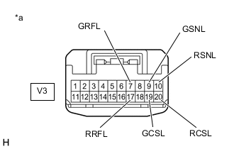
*a Front view of wire harness connector
(to Torque Vectoring Differential ECU Assembly)
Measure the voltage according to the value(s) in the table below.
Standard Voltage Tester Connection Switch Condition Specified Condition V3-17 (RRFL) - Body ground Engine switch on (IG) Below 1 V V3-7 (GRFL) - Body ground Engine switch on (IG) Below 1 V V3-20 (RCSL) - Body ground Engine switch on (IG) Below 1 V V3-19 (GCSL) - Body ground Engine switch on (IG) Below 1 V V3-10 (RSNL) - Body ground Engine switch on (IG) Below 1 V V3-9 (GSNL) - Body ground Engine switch on (IG) Below 1 V Note
Turning the engine switch on (IG) with the torque vectoring differential ECU assembly disconnected causes other DTCs to be stored. Clear the DTCs after performing this inspection.
-
Turn the engine switch off.
-
Measure the resistance according to the value(s) in the table below.
Standard Resistance (Check for Open) Tester Connection Condition Specified Condition V3-17 (RRFL) - V3-7 (GRFL) Always 10 to 12 Ω V3-20 (RCSL) - V3-19 (GCSL) Always 20 to 25 Ω V3-10 (RSNL) - V3-9 (GSNL) Always 19 to 23 Ω Standard Resistance (Check for Short) Tester Connection Condition Specified Condition V3-17 (RRFL) or V3-7 (GRFL) - Body ground and other terminals Always 10 kΩ or higher V3-20 (RCSL) or V3-19 (GCSL) - Body ground and other terminals Always 10 kΩ or higher V3-10 (RSNL) or V3-9 (GSNL) - Body ground and other terminals Always 10 kΩ or higher -
Reconnect the torque vectoring differential ECU assembly connector.
Result Proceed to OK NG
OK
REPLACE TORQUE VECTORING DIFFERENTIAL ECU ASSEMBLY Click here
NG
-
-
CHECK HARNESS AND CONNECTOR (TORQUE VECTORING DIFFERENTIAL ECU ASSEMBLY - TORQUE TRANSFER MODULE MOTOR SUB-ASSEMBLY (LH SIDE))
-
Disconnect the torque vectoring differential ECU assembly connector.
-
Remove the torque vectoring differential FDU (Final Drive Unit).
-
Disconnect the V7 torque transfer module motor sub-assembly (LH side) connector.
-
Turn the engine switch on (IG).
-
*a Front view of wire harness connector
(to Torque Vectoring Differential ECU Assembly)
Measure the voltage according to the value(s) in the table below.
Standard Voltage Tester Connection Switch Condition Specified Condition V3-17 (RRFL) - Body ground Engine switch on (IG) Below 1 V V3-7 (GRFL) - Body ground Engine switch on (IG) Below 1 V V3-20 (RCSL) - Body ground Engine switch on (IG) Below 1 V V3-19 (GCSL) - Body ground Engine switch on (IG) Below 1 V V3-10 (RSNL) - Body ground Engine switch on (IG) Below 1 V V3-9 (GSNL) - Body ground Engine switch on (IG) Below 1 V Note
Turning the engine switch on (IG) with the torque vectoring differential ECU assembly disconnected causes other DTCs to be stored. Clear the DTCs after performing this inspection.
-
Turn the engine switch off.
-
Measure the resistance according to the value(s) in the table below.
Standard Resistance (Check for Open) Tester Connection Condition Specified Condition V3-17 (RRFL) - V7-1 (REFL) Always Below 1 Ω V3-7 (GRFL) - V7-6 (RFGL) Always Below 1 Ω V3-20 (RCSL) - V7-2 (COSL) Always Below 1 Ω V3-19 (GCSL) - V7-7 (CSGL) Always Below 1 Ω V3-10 (RSNL) - V7-3 (SINL) Always Below 1 Ω V3-9 (GSNL) - V7-8 (SNGL) Always Below 1 Ω Standard Resistance (Check for Short) Tester Connection Condition Specified Condition V3-17 (RRFL) or V7-1 (REFL) - Body ground and other terminals Always 10 kΩ or higher V3-7 (GRFL) or V7-6 (RFGL) - Body ground and other terminals Always 10 kΩ or higher V3-20 (RCSL) or V7-2 (COSL) - Body ground and other terminals Always 10 kΩ or higher V3-19 (GCSL) or V7-7 (CSGL) - Body ground and other terminals Always 10 kΩ or higher V3-10 (RSNL) or V7-3 (SINL) - Body ground and other terminals Always 10 kΩ or higher V3-9 (GSNL) or V7-8 (SNGL) - Body ground and other terminals Always 10 kΩ or higher -
Reconnect the V7 torque transfer module motor sub-assembly (LH side) connector.
-
Install the torque vectoring differential FDU (Final Drive Unit).
-
Reconnect the torque vectoring differential ECU assembly connector.
Result Proceed to OK NG
OK
REPLACE TORQUE TRANSFER MODULE MOTOR SUB-ASSEMBLY (LH SIDE) Click here
NG
REPAIR OR REPLACE HARNESS OR CONNECTOR
-