TORQUE VECTORING DIFFERENTIAL SYSTEM, Diagnostic DTC:C2A0D
| DTC Code | DTC Name |
|---|---|
| C2A0D | TVD Relay SW Circuit |
DESCRIPTION
When the engine switch is turned on (IG), the TVD relay is turned on/off for a period of 3 seconds as part of the initial check. This DTC is stored when a malfunction of the TVD relay SW circuit is detected.
| DTC No. | Detection Item | DTC Detection Condition | Trouble Area | Warning Indicate |
|---|---|---|---|---|
| C2A0D | TVD Relay SW Circuit | Diagnosis Condition:
Abnormal condition (1):
Abnormal condition (2):
When all of the following conditions are met: Malfunction Time (1):
Malfunction Time (2):
Trip logic:
|
|
|
| Vehicle Condition | |||
|---|---|---|---|
| Pattern 1 | Pattern 2 | ||
| Diagnosis Condition | IG power source voltage is 10 V and more | ○ | ○ |
| Malfunction Status | PIG voltage is equal to or lower than (IG voltage -1.5 V) when the TVD relay is on | ○ | - |
When all of the following conditions are met: |
- | ○ | |
| Detection Time | 1.25 seconds or more | 2 seconds or more | |
| Number of Trips | 1 trip | 1 trip | |
Tech Tips
DTC will be output when conditions for either of the patterns in the table above are met.
CAUTION / NOTICE / HINT
Tech Tips
If the torque vectoring differential ECU assembly has been replaced, perform "All Learning".
PROCEDURE
-
INSPECT TVD RELAY
-
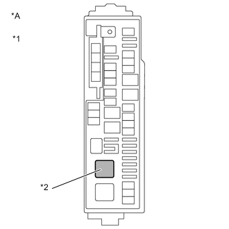
*A for LHD *1 No. 1 Engine Room Relay Block *2 TVD Relay 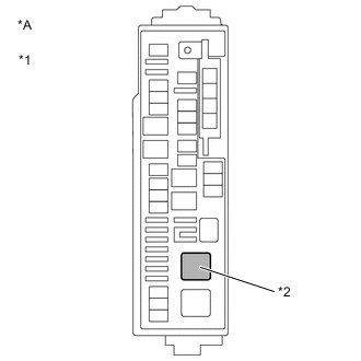
*A for RHD *1 No. 1 Engine Room Relay Block *2 TVD Relay Remove the TVD relay from the No. 1 engine room relay block.
-
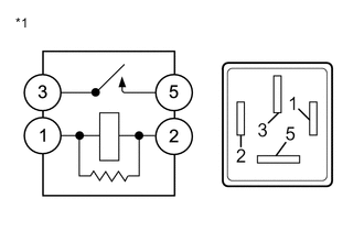
*1 TVD Relay Measure the resistance according to the value(s) in the table below.
Standard Resistance Tester Connection Condition Specified Condition 3 - 5 Battery voltage not applied between terminals 1 and 2 10 kΩ or higher 3 - 5 Battery voltage applied between terminals 1 and 2 Below 1 Ω -
Install the TVD relay.
Result Proceed to OK NG
NG 
REPLACE TVD RELAY
OK 
-
-
CHECK HARNESS AND CONNECTOR (POWER SOURCE CIRCUIT)
-
*A for LHD *1 No. 1 Engine Room Relay Block *2 TVD Relay
*A for RHD *1 No. 1 Engine Room Relay Block *2 TVD Relay Remove the TVD relay from the No. 1 engine room relay block.
-
Turn the engine switch on (IG).
-
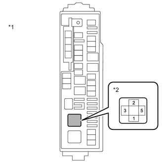
*A for LHD *1 No. 1 Engine Room Relay Block *2 TVD Relay Holder 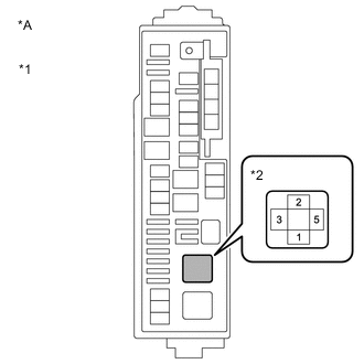
*A for RHD *1 No. 1 Engine Room Relay Block *2 TVD Relay Holder Measure the voltage according to the value(s) in the table below.
Standard Voltage Tester Connection Switch Condition Specified Condition 1 (TVD relay holder) - Body ground Engine switch on (IG) 10 to 14 V 3 (TVD relay holder) - Body ground Engine switch on (IG) 10 to 14 V -
Turn the engine switch off.
-
Install the TVD relay.
Result Proceed to OK NG
NG
REPAIR OR REPLACE POWER SOURCE CIRCUIT
OK
-
-
CHECK HARNESS AND CONNECTOR (TVD RELAY - TORQUE VECTORING DIFFERENTIAL ECU ASSEMBLY)
-
*A for LHD *1 No. 1 Engine Room Relay Block *2 TVD Relay
*A for RHD *1 No. 1 Engine Room Relay Block *2 TVD Relay Remove the TVD relay from the No. 1 engine room relay block.
-
Disconnect the U42 and U43 torque vectoring differential ECU assembly connectors.
-
Measure the resistance according to the value(s) in the table below.
Standard Resistance (Check for Open) Tester Connection Condition Specified Condition 5 (TVD relay holder) - U42-1 (PIG) Always Below 1 Ω 5 (TVD relay holder) - U42-4 (PIG1) Always Below 1 Ω 2 (TVD relay holder) - U43-7 (PIGR) Always Below 1 Ω Standard Resistance (Check for Short) Tester Connection Condition Specified Condition 5 (TVD relay holder) - 2 (TVD relay holder) Always 10 kΩ or higher 5 (TVD relay holder) - Body ground Always 10 kΩ or higher 2 (TVD relay holder) - Body ground Always 10 kΩ or higher -
Reconnect the U42 and U43 torque vectoring differential ECU assembly connectors.
-
Install the TVD relay.
Result Proceed to OK NG
OK
REPLACE TORQUE VECTORING DIFFERENTIAL ECU ASSEMBLY Click here
NG
REPAIR OR REPLACE HARNESS OR CONNECTOR
-