TORQUE VECTORING DIFFERENTIAL SYSTEM, Diagnostic DTC:C2A13, C2A18
| DTC Code | DTC Name |
|---|---|
| C2A13 | RH Oil Temperature Sensor Circuit (High) |
| C2A18 | LH Oil Temperature Sensor Circuit (High) |
DESCRIPTION
If an open in the torque transfer module temperature sensor is detected, a DTC is stored.
| DTC No. | Detection Item | DTC Detection Condition | Trouble Area | Warning Indicate |
|---|---|---|---|---|
| C2A13 | RH Oil Temperature Sensor Circuit (High) | Diagnosis Condition:
Abnormal condition:
Malfunction Time:
Trip logic:
|
|
|
| C2A18 | LH Oil Temperature Sensor Circuit (High) | Diagnosis Condition:
Abnormal condition:
Malfunction Time:
Trip logic:
|
|
|
CAUTION / NOTICE / HINT
Tech Tips
-
If the torque vectoring differential ECU assembly has been replaced, perform "All Learning".
-
If the torque transfer module motor sub-assembly has been replaced or removed and installed, perform "Motor Exchange Learning".
PROCEDURE
-
CHECK DTC OUTPUT (TVD)
-
Connect the GTS to the DLC3.
-
Turn the engine switch on (IG).
-
Enter the following menus: Chassis / TVD / Trouble Codes.
-
Check for DTCs.
Chassis > TVD > Trouble CodesResult Result Proceed to DTC C2A13 is output. A DTC C2A18 is output. B -
Turn the engine switch off.
B 
INSPECT TEMPERATURE SENSOR (LH SIDE) Click here
A 
-
-
INSPECT TEMPERATURE SENSOR (RH SIDE)
-
Disconnect the torque transfer module motor sub-assembly (RH side) connector.
-
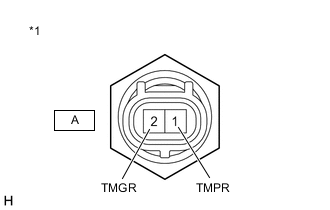
*1 Temperature Sensor (RH Side) Measure the resistance according to the value(s) in the table below.
Standard Resistance Tester Connection Condition Specified Condition A-1 (TMPR) - A-2 (TMGR) 0°C (32°F) to 155°C (311°F) 0.2 to 30.8 kΩ -
Reconnect the torque transfer module motor sub-assembly (RH side) connector.
Result Proceed to OK NG
NG 
REPLACE TEMPERATURE SENSOR (RH SIDE) Click here
OK
-
-
CHECK TORQUE TRANSFER MODULE MOTOR SUB-ASSEMBLY (RH SIDE) (HARNESS AND CONNECTOR)
-
Remove the torque vectoring differential FDU (Final Drive Unit).
-
Disconnect the torque transfer module motor sub-assembly (RH side) connectors.
-
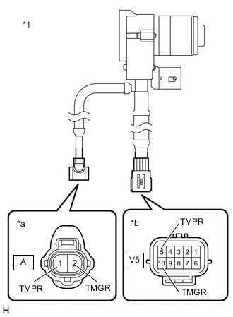
*1 Torque Transfer Module Motor Sub-assembly (RH Side) *a Temperature Sensor (RH Side) Connector *b TVD Sensor Connector Measure the resistance according to the value(s) in the table below.
Standard Resistance Tester Connection Condition Specified Condition V5-5 (TMPR) - A-1 (TMPR) Always Below 1 Ω V5-10 (TMGR) - A-2 (TMGR) Always Below 1 Ω -
Reconnect the torque transfer module motor sub-assembly (RH side) connectors.
-
Install the torque vectoring differential FDU (Final Drive Unit).
Result Proceed to OK NG
NG
REPLACE TORQUE TRANSFER MODULE MOTOR SUB-ASSEMBLY (RH SIDE) Click here
OK
-
-
CHECK HARNESS AND CONNECTOR (TORQUE VECTORING DIFFERENTIAL ECU ASSEMBLY - TORQUE TRANSFER MODULE MOTOR SUB-ASSEMBLY (RH SIDE))
-
Disconnect the V3 torque vectoring differential ECU assembly connector.
-
Remove the torque vectoring differential FDU (Final Drive Unit).
-
Disconnect the V5 torque transfer module motor sub-assembly (RH side) connector.
-
Measure the resistance according to the value(s) in the table below.
Standard Resistance Tester Connection Condition Specified Condition V3-15 (OTR) - V5-5 (TMPR) Always Below 1 Ω V3-5 (OTRG) - V5-10 (TMGR) Always Below 1 Ω -
Reconnect the V5 torque transfer module motor sub-assembly (RH side) connector.
-
Install the torque vectoring differential FDU (Final Drive Unit).
-
Reconnect the V3 torque vectoring differential ECU assembly connector.
Result Proceed to OK NG
OK
REPLACE TORQUE VECTORING DIFFERENTIAL ECU ASSEMBLY Click here
NG
REPAIR OR REPLACE HARNESS OR CONNECTOR
-
-
INSPECT TEMPERATURE SENSOR (LH SIDE)
-
Disconnect the torque transfer module motor sub-assembly (LH side) connector.
-
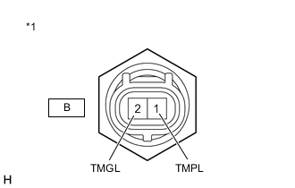
*1 Temperature Sensor (LH Side) Measure the resistance according to the value(s) in the table below.
Standard Resistance Tester Connection Condition Specified Condition B-1 (TMPL) - B-2 (TMGL) 0°C (32°F) to 155°C (311°F) 0.2 to 30.8 kΩ -
Reconnect the torque transfer module motor sub-assembly (LH side) connector.
Result Proceed to OK NG
NG
REPLACE TEMPERATURE SENSOR (LH SIDE) Click here
OK
-
-
CHECK TORQUE TRANSFER MODULE MOTOR SUB-ASSEMBLY (LH SIDE) (HARNESS AND CONNECTOR)
-
Remove the torque vectoring differential FDU (Final Drive Unit).
-
Disconnect the torque transfer module motor sub-assembly (LH side) connectors.
-

*1 Torque Transfer Module Motor Sub-assembly (LH Side) *a Temperature Sensor (LH Side) Connector *b TVD Sensor Connector Measure the resistance according to the value(s) in the table below.
Standard Resistance Tester Connection Condition Specified Condition V7-5 (TMPL) - B-1 (TMPL) Always Below 1 Ω V7-10 (TMGL) - B-2 (TMGL) Always Below 1 Ω -
Reconnect the torque transfer module motor sub-assembly (LH side) connectors.
-
Install the torque vectoring differential FDU (Final Drive Unit).
Result Proceed to OK NG
NG
REPLACE TORQUE TRANSFER MODULE MOTOR SUB-ASSEMBLY (LH SIDE) Click here
OK
-
-
CHECK HARNESS AND CONNECTOR (TORQUE VECTORING DIFFERENTIAL ECU ASSEMBLY - TORQUE TRANSFER MODULE MOTOR SUB-ASSEMBLY (LH SIDE))
-
Disconnect the V3 torque vectoring differential ECU assembly connector.
-
Remove the torque vectoring differential FDU (Final Drive Unit).
-
Disconnect the V7 torque transfer module motor sub-assembly (LH side) connector.
-
Measure the resistance according to the value(s) in the table below.
Standard Resistance Tester Connection Condition Specified Condition V3-6 (OTL) - V7-5 (TMPL) Always Below 1 Ω V3-16 (OTLG) - V7-10 (TMGL) Always Below 1 Ω -
Reconnect the V7 torque transfer module motor sub-assembly (LH side) connector.
-
Install the torque vectoring differential FDU (Final Drive Unit).
-
Reconnect the V3 torque vectoring differential ECU assembly connector.
Result Proceed to OK NG
OK
REPLACE TORQUE VECTORING DIFFERENTIAL ECU ASSEMBLY Click here
NG
REPAIR OR REPLACE HARNESS OR CONNECTOR
-