REAR DIFFERENTIAL CARRIER ASSEMBLY REMOVAL

CAUTION / NOTICE / HINT
The necessary procedures (adjustment, calibration, initialization, or registration) that must be performed after parts are removed, installed, or replaced during the torque vectoring differential FDU (Final Drive Unit) removal/installation are shown below.
| Replacement Part or Procedure | Necessary Procedure | Effect/Inoperative when not Performed | Link |
|---|---|---|---|
| Disconnect cable from negative battery terminal | Memorize steering angle neutral point | Parking assist monitor system | |
| Lane departure alert system (w/ Steering Control) | |||
| Pre-crash safety system | |||
| Adaptive high beam system | |||
| Reset power trunk lid | Power trunk lid system | ||
| Removal/installation of torque transfer module motor sub-assembly | Motor exchange learning | Torque vectoring differential system | |
| Replacement of torque vectoring differential FDU (Final Drive Unit) | ASSY exchange learning | ||
| Removal/installation of rear disc | Parking brake bedding | Electric parking brake system | |
| Rear wheel alignment adjustment |
|
|
|
| Removal/installation of rear height control sensor sub-assembly | Perform headlight control computer assembly LH initialization | Headlight leveling function |
PROCEDURE
-
PRECAUTION
Note
After turning the engine switch off, waiting time may be required before disconnecting the cable from the negative (-) battery terminal. Therefore, make sure to read the disconnecting the cable from the negative (-) battery terminal notices before proceeding with work.
-
DISCONNECT CABLE FROM NEGATIVE BATTERY TERMINAL
Note
When disconnecting the cable, some systems need to be initialized after the cable is reconnected.
-
DRAIN TORQUE TRANSFER MODULE FLUID
-
DRAIN DIFFERENTIAL OIL
-
REMOVE LUGGAGE COMPARTMENT FLOOR MAT (w/o Spare Tire)
-
REMOVE LUGGAGE COMPARTMENT FLOOR MAT (w/ Spare Tire)
-
REMOVE LUGGAGE COMPARTMENT TRIM BOX (w/o Spare Tire)
-
REMOVE SPARE WHEEL COVER TRAY (w/o Spare Tire)
-
REMOVE SPARE WHEEL COVER TRAY (w/ Spare Tire)
-
REMOVE SPARE TIRE (w/ Spare Tire)
-
REMOVE NO. 1 FLOOR UNDER COVER ASSEMBLY
-
REMOVE ECU BRACKET (w/ Spare Tire)
-
DISCONNECT NO. 4 FLOOR WIRE
-
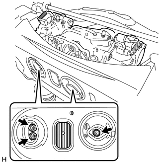
Disconnect the connector (A).
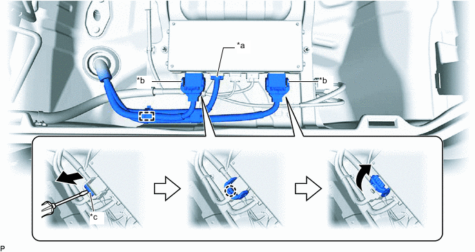
*a Connector (A) *b Connector (B) *c Lock - - -
Using a screwdriver, release the 2 locks and disconnect the 2 connectors (B) as shown in the illustration.
Tech Tips
When disconnecting the connector with lock lever, pull out the lock of the lock lever, disengage the claw and turn the lock lever to disconnect the connector as shown in the illustration.
-
Disengage the clamp.
-
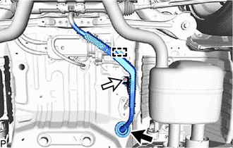

Grommet 
Nut Disengage the grommet.
-
Disengage the clamp.
-
Remove the nut and disconnect the No. 4 floor wire.
-
Pass the No. 4 floor wire through the grommet hole to the outside of the vehicle.
Tech Tips
Use wire or an equivalent tool to keep the No. 4 floor wire from hanging from the vehicle body.
-
-
REMOVE REAR SUSPENSION MEMBER SUB-ASSEMBLY
-
REMOVE NO. 4 FLOOR WIRE
-
Remove the 6 bolts.

*a Connector (A) *b Connector (B) *c Lock - - -
Disengage the 2 clamps.
-
Disconnect the 2 connectors (A).
-
Using a screwdriver, release the 2 locks and disconnect the 2 connectors (B) as shown in the illustration to remove the No. 4 floor wire.
Tech Tips
When disconnecting the connector with lock lever, pull out the lock of the lock lever, disengage the claw and turn the lock lever to disconnect the connector as shown in the illustration.
-
-
REMOVE REAR SUSPENSION ARM BRACKET ASSEMBLY
-
REMOVE TORQUE VECTORING DIFFERENTIAL FDU (FINAL DRIVE UNIT)
Note
-
Do not damage the installation surface when removing the torque vectoring differential FDU (Final Drive Unit).
-
The remaining oil may leak out when removing the torque vectoring differential FDU (Final Drive Unit).
-
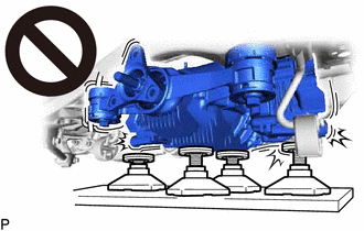
Securely support the torque vectoring differential FDU (Final Drive Unit) while performing this step to avoid excessively tilting or dropping the torque vectoring differential FDU (Final Drive Unit).
-
Remove the bolts with the torque vectoring differential FDU (Final Drive Unit) secured.
-
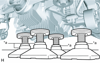
*a Attachment Support the torque vectoring differential FDU (Final Drive Unit) with 4 attachments or equivalent tools as shown in the illustration.
CAUTION:
-
The torque vectoring differential FDU (Final Drive Unit) is a heavy component. Make sure that it is supported securely.
-
If the torque vectoring differential FDU (Final Drive Unit) is not securely supported, it may drop, resulting in serious injury.
Note
Use attachments or equivalent tools to keep the torque vectoring differential FDU (Final Drive Unit) level.
-
-
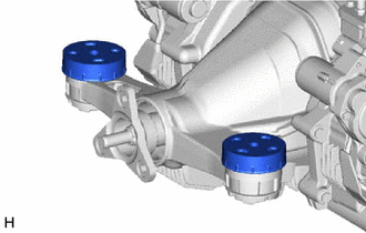
Using a 12 mm hexagon socket wrench, remove the 3 bolts.
-
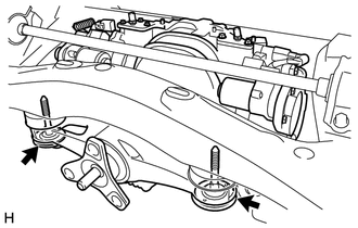
Remove the 2 bolts and 2 rear lower differential mount stoppers.
-
Remove the rear suspension member sub-assembly from the torque vectoring differential FDU (Final Drive Unit).
-
Remove the 2 rear upper differential mount stoppers.
-
-
REMOVE REAR DIFFERENTIAL FILLER PLUG (for Upper Side)
-
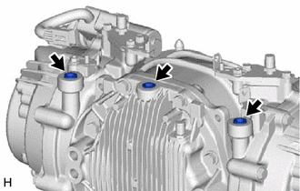
Using an 8 mm hexagon socket wrench, remove the 3 rear differential filler plugs from the torque vectoring differential FDU (Final Drive Unit).
-
-
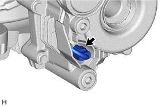
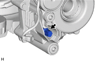
REMOVE REAR DIFFERENTIAL BREATHER PLUG
-
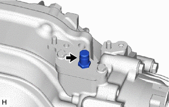
Remove the rear differential breather plug from the rear differential carrier.
Tech Tips
Use the same procedure for the other side.
-
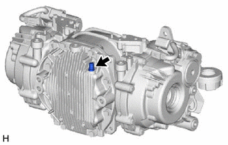
Remove the rear differential breather plug from the rear differential carrier cover.
-
-
REMOVE REAR DIFFERENTIAL CARRIER COVER
-
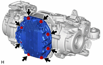
Remove the 8 bolts.
-
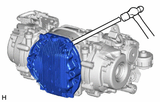
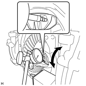
Using a brass bar and a hammer, remove the rear differential carrier cover from the rear differential carrier.
Note
-
Place the brass bar onto the corners of the rear differential carrier cover.
-
Do not damage the contact surface.
-
-
-
INSPECT RUNOUT OF DIFFERENTIAL RING GEAR
-
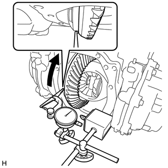
Set a dial indicator perpendicular to the end of the differential ring gear face.
-
Rotate the differential ring gear and measure the runout.
Maximum Runout 0.05 mm (0.00197 in.) If the runout is more than the maximum, replace the torque vectoring differential FDU (Final Drive Unit).
-
-
INSPECT DIFFERENTIAL RING GEAR BACKLASH
-
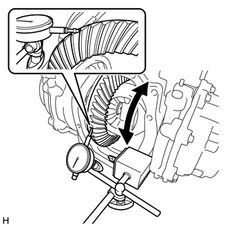
While holding the rear drive pinion companion flange, rotate the differential ring gear and measure the ring gear backlash.
Standard Backlash 0.08 to 0.13 mm (0.00315 to 0.00511 in.) If the ring gear backlash is not within the specified range, replace the torque vectoring differential FDU (Final Drive Unit).
-
-
INSPECT TOOTH CONTACT BETWEEN RING GEAR AND DRIVE PINION
-
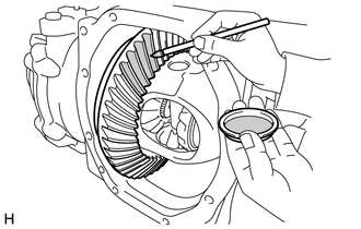
Coat 3 or 4 teeth at 3 different positions on the differential ring gear with Prussian blue.
-
Rotate the differential ring gear in both directions.
-
Inspect the tooth contact pattern.
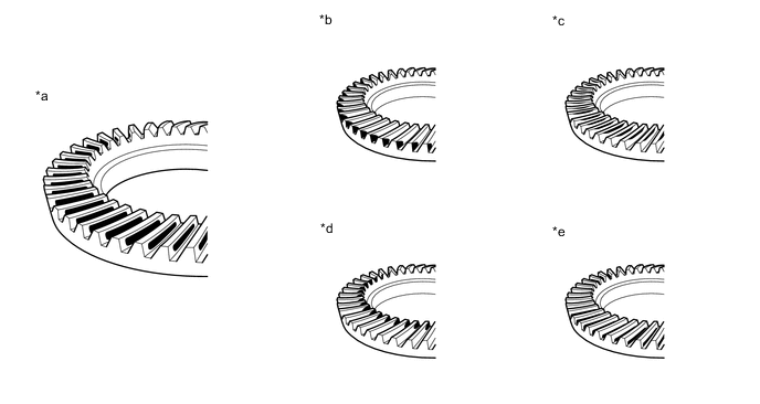
*a Proper Contact *b Heel Contact *c Face Contact *d Toe Contact *e Flank Contact - - Note
Check the tooth contact pattern at 4 or more positions around circumference of the differential ring gear.
If the teeth are not contacting properly, replace the torque vectoring differential FDU (Final Drive Unit).
-
-
INSPECT DIFFERENTIAL SIDE GEAR BACKLASH
-
Place a dial indicator on the tip of a side gear tooth at a right angle. Hold the pinion gear in the rear differential case sub-assembly and check that the backlash is 0 mm (0 in.).
If the result is not as specified, replace the torque vectoring differential FDU (Final Drive Unit).
-
-
INSPECT RUNOUT OF DIFFERENTIAL DRIVE PINION
-
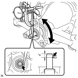
*a 10 mm (0.394 in.) Using a dial indicator, measure the runout of the differential drive pinion at a position 10 mm (0.394 in.) away from the end of the differential drive pinion.
Maximum Runout 0.08 mm (0.00315 in.) If the runout is more than the maximum, replace the torque vectoring differential FDU (Final Drive Unit).
-
-
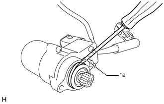
INSPECT TOTAL PRELOAD
-
Turn the bearing clockwise and counterclockwise several times to stabilize it.
-
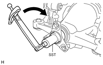
Using SST and a torque wrench, turn the differential drive pinion continuously at a rate of 1 second per turn and measure the total preload.
- SST
- 09229-55010
Standard Total Preload 4.38 N*m (45 kgf*cm, 39 in.*lbf) or less If the total preload is not within the specified range, replace the torque vectoring differential FDU (Final Drive Unit).
-
-
REMOVE REAR DRIVE SHAFT OIL SEAL LH
-
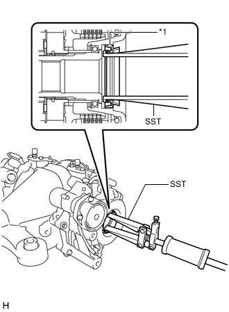
*1 Rear Drive Shaft Oil Seal LH Using SST, remove the rear drive shaft oil seal LH.
- SST
- 09308-00010
-
-
REMOVE REAR DRIVE SHAFT OIL SEAL RH
Tech Tips
Use the same procedure as for the LH side.
-
REMOVE TORQUE TRANSFER MODULE MOTOR SUB-ASSEMBLY (for LH Side)
-
Disconnect the connector.
-
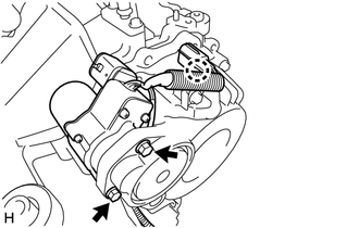
Disengage the claw and separate the connector.
-
Remove the 2 bolts and torque transfer module motor sub-assembly.
-
*a Protective Tape Using a screwdriver with its tip wrapped with protective tape, remove the O-ring.
Note
Do not damage the torque transfer module motor sub-assembly installation surface.
-
-
REMOVE TORQUE TRANSFER MODULE MOTOR SUB-ASSEMBLY (for RH Side)
Tech Tips
Use the same procedure as for the LH side.
-
REMOVE TEMPERATURE SENSOR (for LH Side)
-
Using a 22 mm deep socket wrench, remove the temperature sensor and gasket.
-
-
REMOVE TEMPERATURE SENSOR (for RH Side)
Tech Tips
Use the same procedure as for the LH side.