FUEL PUMP REASSEMBLY

PROCEDURE
-
INSTALL FUEL MAIN VALVE ASSEMBLY
-
Apply a light coat of gasoline to 2 new O-rings and install them to the fuel main valve assembly.
-
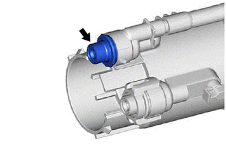
Install the fuel main valve assembly to the fuel filter.
Note
-
If the fuel main valve assembly and fuel pressure regulator assembly are mistakenly interchanged when they are installed, the engine may stall. Always make sure the installation positions are correct.
-
When installing the O-ring, make sure that it does not become pinched or cut.
-
-
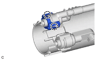
Engage the 2 claws to install the No. 2 fuel suction support to the fuel filter.
Note
Securely engage the claws.
-
-
INSTALL FUEL PUMP WITH FILTER ASSEMBLY
Tech Tips
Perform "Inspection After Repair" after replacing the fuel pump with filter assembly.
-
w/ Canister Pump Module:
-
w/o Canister Pump Module:
-
Apply a light coat of gasoline to a new O-ring. Then install the O-ring to the fuel pump with filter assembly.
-
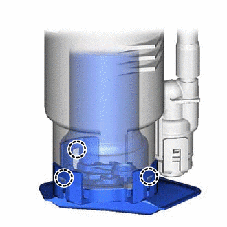
Engage the 3 claws to install the fuel pump with filter assembly to the fuel filter.
Note
-
Make sure that the O-ring is not cut or pinched during installation.
-
Engage the claws securely.
-
Do not remove the suction filter.
-
-
-
INSTALL NO. 1 FUEL SUCTION SUPPORT
-
Engage the 2 claws to install the No. 1 fuel suction support to the fuel filter.
-
-
INSTALL JET PUMP
-
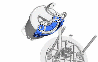
Apply a light coat of gasoline to a new O-ring and install the O-ring to the jet pump.
-
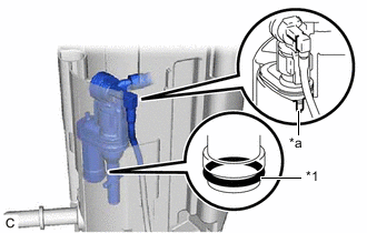
*1 O-ring *a Notch Install the jet pump to the No. 1 fuel sub-tank as shown in the illustration.
Note
Make sure that the O-ring is not cut or pinched during installation.
-
Engage the claw and install the fuel tube to the No. 1 fuel sub-tank.
Note
Securely engage the claw.
-
-
INSTALL FUEL FILTER
-
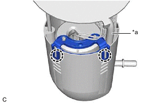
*a Tube Engage the 2 claws to install the fuel filter and fuel pump with filter assembly to the No. 1 fuel sub-tank.
Note
-
Do not apply excessive force to the tube or No. 1 fuel suction support.
-
Securely engage the claws.
-
-
-
INSTALL FUEL SUCTION PLATE SUB-ASSEMBLY
-
Install the spring to the fuel suction plate shaft.
-
Install the fuel suction plate sub-assembly to the No. 1 fuel sub-tank.
-
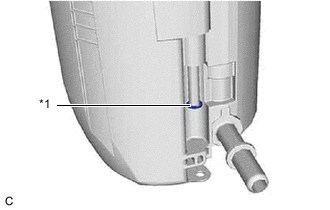
*1 E-ring Install a new E-ring to the fuel suction plate shaft.
-
Connect the fuel pump harness connector.
Note
Make sure that the fuel pump harness connector is engaged securely.
-
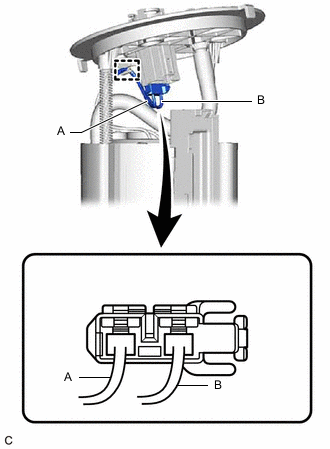
Engage the clamp to connect the fuel pump harness to the fuel suction plate sub-assembly as shown in the illustration.
Note
-
Engage the connector (A) first and then (B) when connecting the fuel pump harness to the clamp.
-
Do not twist or excessively pull the fuel pump harness.
-
-
-
INSTALL FUEL SENDER GAUGE ASSEMBLY