FUEL PUMP REMOVAL

CAUTION / NOTICE / HINT
The necessary procedures (adjustment, calibration, initialization, or registration) that must be performed after parts are removed, installed, or replaced during the fuel pump with filter assembly removal/installation are shown below.
| Replacement Part or Procedure | Necessary Procedure | Effect/Inoperative when not Performed | Link |
|---|---|---|---|
| Disconnect cable from negative battery terminal | Memorize steering angle neutral point | Parking assist monitor system | |
| LKA/LDA system | |||
| Pre-crash safety system | |||
| Adaptive high beam system | |||
| Reset power trunk lid | Power trunk lid system | ||
| Replacement of fuel pump with filter assembly (for low pressure side) | Inspection After Repair |
|
|
CAUTION:
-
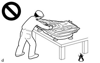
Never perform work on fuel system components near any possible ignition sources.
-
Vaporized fuel could ignite, resulting in a serious accident.
-
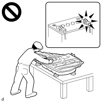
Do not perform work on fuel system components without first disconnecting the cable from the negative (-) battery terminal.
-
Sparks could cause vaporized fuel to ignite, resulting in a serious accident.
PROCEDURE
-
PRECAUTION
Note
After turning the engine switch off, waiting time may be required before disconnecting the cable from the negative (-) battery terminal. Therefore, make sure to read the disconnecting the cable from the negative (-) battery terminal notices before proceeding with work.
-
DISCHARGE FUEL SYSTEM PRESSURE
-
DISCONNECT CABLE FROM NEGATIVE BATTERY TERMINAL
Note
When disconnecting the cable, some systems need to be initialized after the cable is reconnected.
-
REMOVE REAR SEAT ASSEMBLY
-
REMOVE REAR FLOOR SERVICE HOLE COVER
-
*a Protective Tape Using a clip remover with its tip wrapped with protective tape, remove the rear floor service hole cover and butyl tape.
-
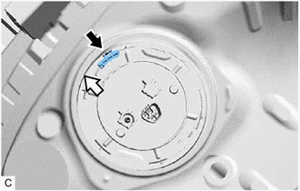
Disconnect the fuel pump connector.
-
-
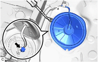
DISCONNECT FUEL TANK MAIN TUBE SUB-ASSEMBLY
-
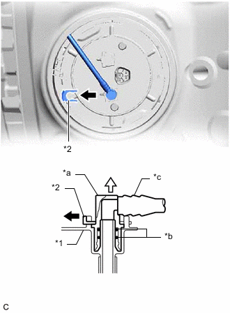
*1 Fuel Suction Plate Sub-assembly *2 Tube Joint Clip *a Fuel Tube Joint *b O-ring *c Nylon Tube 
Pull off 
Pull off Remove the tube joint clip, and pull off the fuel tube joint of the fuel tank main tube sub-assembly.
Note
-
Remove any foreign matter on the fuel tube joint before performing this work.
-
Do not allow any scratches or foreign matter to get on the parts when disconnecting them as the fuel tube joint has O-rings that seal the plug.
-
Be sure to disconnect the fuel tube joint by hand.
-
Do not forcibly bend, twist or turn the nylon tube.
-
Protect the disconnected part by covering it with a plastic bag after disconnecting the fuel tube joint.
-
If the fuel tube joint and fuel suction plate sub-assembly are stuck, push and pull to release them.
-
-
-
REMOVE FUEL PUMP GAUGE RETAINER
-
Front Side Release the lock to remove the No. 1 fuel tube clamp.
-
Remove the fuel pump gauge retainer.
-
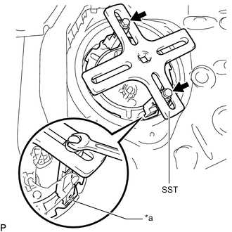
*a Insertion Point SST (Bolt) Set the 2 claws, 2 bolts and plate of SST on the fuel pump gauge retainer.
- SST
- 09808-14031 ( 09808-01010, 09808-01020, 09808-01030, 09808-01090 )
- 09808-01071
Tech Tips
Securely insert the ends of SST (claw) into the insertion points in the fuel pump gauge retainer.
-
While firmly pressing SST (claw) into the insertion points in the fuel pump gauge retainer, tighten SST (bolt).
-
Attach the handle of SST.
-
Check once more that the tip of SST is securely inserted into the insertion area of the fuel pump gauge retainer as shown in the illustration.
-
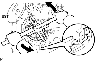
While lightly pressing down on SST so it does not come off the retainer, slowly turn the handle and remove the fuel pump gauge retainer.
Note
-
Do not use any tools other than specified in this operation as this may result in damage to the fuel pump gauge retainer or the fuel tank assembly.
-
Do not press down on SST excessively as this may make the fuel pump gauge retainer hard to rotate, and may damage components.
-
Make sure to rotate SST (handle) horizontally. If it is rotated at an angle, SST may come off.
-
Do not spin SST too fast or use an impact wrench as this may result in damage to components.
-
If SST comes off of the fuel pump gauge retainer, loosen SST (bolt) and reinstall SST.
-
-
While pressing down on the fuel suction tube with pump and gauge assembly, remove the fuel pump gauge retainer.
-
-
-
REMOVE FUEL SUCTION TUBE WITH PUMP AND GAUGE ASSEMBLY
-
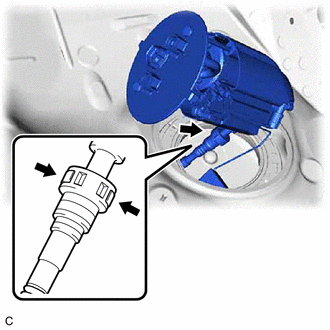
Disconnect the fuel return vent tube sub-assembly and remove the fuel suction tube with pump and gauge assembly from the fuel tank assembly.
Note
-
Make sure that the fuel sender gauge assembly arm does not bend.
-
Do not damage the fuel return vent tube sub-assembly.
-
When disconnecting the fuel tube connector, do not excessively pull on the fuel return vent tube sub-assembly.
-
-
Remove the fuel suction tube set gasket from the fuel tank assembly.
-