FUEL INJECTOR(for Port Injection) REMOVAL

CAUTION / NOTICE / HINT
The necessary procedures (adjustment, calibration, initialization, or registration) that must be performed after parts are removed, installed, or replaced during the port fuel injector assembly removal/installation are shown below.
| Replacement Part or Procedure | Necessary Procedure | Effect/Inoperative when not Performed | Link |
|---|---|---|---|
| Disconnect cable from negative battery terminal | Memorize steering angle neutral point | Parking assist monitor system | |
| Lane departure alert system (w/ Steering Control) | |||
| Pre-crash safety system | |||
| Adaptive high beam system | |||
| Reset power trunk lid | Power trunk lid system | ||
| Replacement of port fuel injector assembly | Inspection After Repair |
|
|
CAUTION:
-
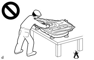
Never perform work on fuel system components near any possible ignition sources.
-
Vaporized fuel could ignite, resulting in a serious accident.
-
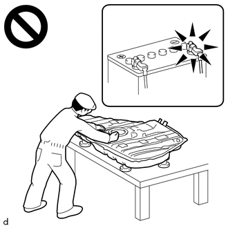
Do not perform work on fuel system components without first disconnecting the cable from the negative (-) battery terminal.
-
Sparks could cause vaporized fuel to ignite, resulting in a serious accident.
PROCEDURE
-
DISCHARGE FUEL SYSTEM PRESSURE
-
PRECAUTION
Note
After turning the engine switch off, waiting time may be required before disconnecting the cable from the negative (-) battery terminal. Therefore, make sure to read the disconnecting the cable from the negative (-) battery terminal notices before proceeding with work.
-
DISCONNECT CABLE FROM NEGATIVE BATTERY TERMINAL
Note
When disconnecting the cable, some systems need to be initialized after the cable is reconnected.
-
DISCONNECT NO. 2 FUEL TUBE SUB-ASSEMBLY
Note
Remove any dirt or foreign matter on the fuel tube connector and fuel pipe before performing this work.
-
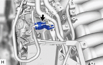
Remove the EFI fuel pipe clamp from fuel tube connector.
-
Check that there is no dirt or other foreign matter around the fuel tube connector before disconnecting it. Clean the joint if necessary.
-
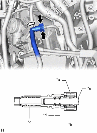
*a Retainer *b Fuel Tube Connector *c Nylon Tube *d O-ring *e Fuel Pipe 
Pinch 
Pull Disconnect the No. 2 fuel tube sub-assembly from the fuel delivery pipe sub-assembly.
-
Pinch the retainer of the fuel tube connector, and then pull the fuel tube connector off of the fuel pipe.
Note
Be sure to disconnect the fuel tube connector by hand.
-
If the fuel tube connector and fuel pipe are stuck, push and pull the fuel tube connector to release it. Pull the fuel tube connector off of the fuel pipe carefully.
Note
-
Be sure to disconnect the fuel tube connector by hand.
-
Do not allow any scratches or foreign matter to get on the parts when disconnecting them as the fuel tube connector has O-rings that seal the fuel pipe.
-
Do not forcibly bend, twist or turn the nylon tube.
-
-
Check if there is any foreign matter on the sealing surfaces of the disconnected fuel lines. Clean them if necessary.
-
Cover the disconnected fuel pipe and fuel tube connector with plastic bags to prevent damage and contamination.
-
-
-
REMOVE THROTTLE BODY WITH MOTOR ASSEMBLY
-
DISENGAGE ENGINE WIRE
-
REMOVE INJECTOR DRIVER
-
REMOVE INJECTOR DRIVER BRACKET
-
REMOVE WATER BY-PASS PIPE SUB-ASSEMBLY
-
REMOVE PURGE VALVE (PURGE VSV)
-
REMOVE FUEL TUBE SUB-ASSEMBLY
-
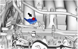
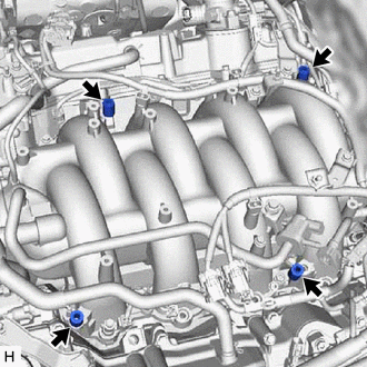
Remove the bolt and separate the wire harness bracket from the intake air surge tank assembly.
-
for LHD:
-
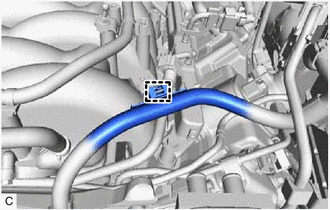
Disengage the clamp to disconnect the wire harness.
-
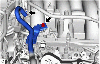
Remove the bolt and wire harness bracket from the intake air surge tank assembly.
-
-
for RHD:
-
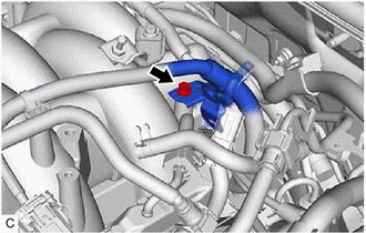
Slide the clip and disconnect the union to check valve hose from the intake air surge tank assembly.
-
Remove the bolt and separate the wire harness bracket from the intake air surge tank assembly.
-
-
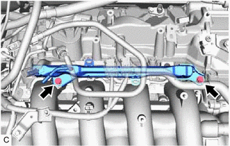
Remove the fuel tube sub-assembly from the fuel delivery pipe sub-assembly and No. 2 fuel delivery pipe sub-assembly.
Note
Remove any dirt or foreign matter on the fuel tube connector and fuel pipe before performing this work.
-
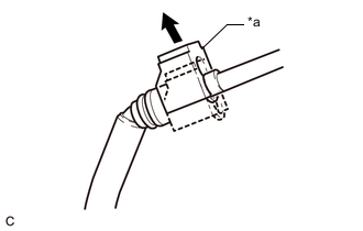
*a Fuel Tube Connector Cover Pull off Pull off the fuel tube connector cover.
-
Pinch the retainer of the fuel tube connector, and then pull the fuel tube connector off of the fuel pipe.
Note
Be sure to disconnect the fuel tube connector by hand.
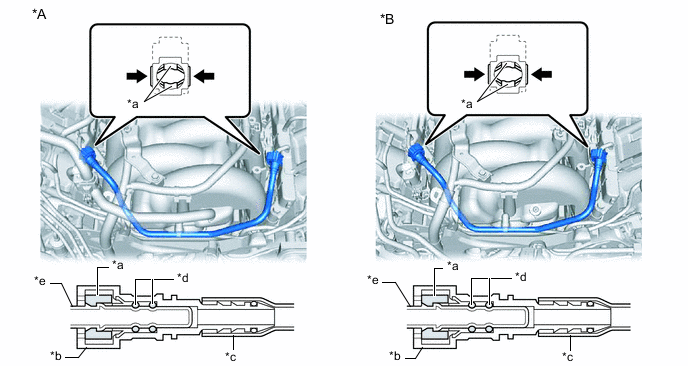
*A for LHD *B for RHD *a Retainer *b Fuel Tube Connector *c Nylon Tube *d O-ring *e Fuel Pipe - - Pinch - - -
If the fuel tube connector and fuel pipe are stuck, push and pull the fuel tube connector to release it. Pull the fuel tube connector off of the fuel pipe carefully.
Note
-
Be sure to disconnect the fuel tube connector by hand.
-
Do not allow any scratches or foreign matter to get on the parts when disconnecting them as the fuel tube connector has O-rings that seal the fuel pipe.
-
Do not forcibly bend, twist or turn the nylon tube.
-
-
Check if there is any foreign matter on the sealing surfaces of the disconnected fuel lines. Clean them if necessary.
-
Cover the disconnected fuel pipe and fuel tube connector with plastic bags to prevent damage and contamination.
-
-
-
REMOVE NO. 2 FUEL DELIVERY PIPE SUB-ASSEMBLY
-
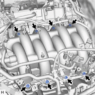
Remove the 2 bolts and No. 2 fuel delivery pipe sub-assembly with the port fuel injector assemblies.
Note
Be careful not to drop the port fuel injector assemblies when removing the No. 2 fuel delivery pipe sub-assembly.
-
-
REMOVE FUEL DELIVERY PIPE SUB-ASSEMBLY
-
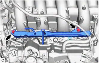
Remove the 2 bolts and fuel delivery pipe sub-assembly with the port fuel injector assemblies.
Note
Be careful not to drop the port fuel injector assemblies when removing the fuel delivery pipe sub-assembly.
-
-
REMOVE NO. 1 DELIVERY PIPE SPACER
-
Remove the 4 No. 1 delivery pipe spacers from the intake air surge tank assembly.
-
-
REMOVE INJECTOR VIBRATION INSULATOR
-
Remove the 8 injector vibration insulators from the intake air surge tank assembly.
-
-
REMOVE PORT FUEL INJECTOR ASSEMBLY
-
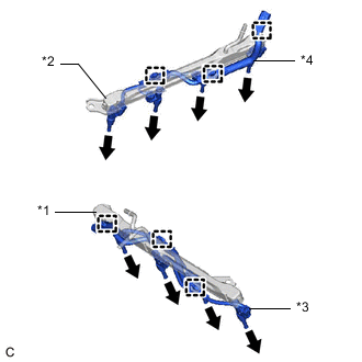
*1 Fuel Delivery Pipe Sub-assembly *2 No. 2 Fuel Delivery Pipe Sub-assembly *3 No. 6 Engine Wire *4 No. 7 Engine Wire Disengage the 3 clamps and disconnect the No. 6 engine wire from the fuel delivery pipe sub-assembly.
-
Disengage the 3 clamps and disconnect the No. 7 engine wire from the No. 2 fuel delivery pipe sub-assembly.
-
Remove the 8 port fuel injector assemblies from the fuel delivery pipe sub-assembly and No. 2 fuel delivery pipe sub-assembly.
Note
If the port fuel injector assemblies are to be reused, reinstall them to the same cylinder they were removed from.
-
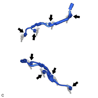
Disconnect the 8 port fuel injector assembly connectors.
-
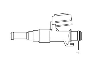
*1 O-ring Remove the O-ring from each port fuel injector assembly.
-
For reinstallation, attach a tag or label with the corresponding cylinder number to each port fuel injector assembly.
Note
Protect the port fuel injector assemblies by covering them with plastic bags.
-