CYLINDER HEAD DISASSEMBLY

CAUTION / NOTICE / HINT
The necessary procedures (adjustment, calibration, initialization, or registration) that must be performed after parts are removed, installed, or replaced during the cylinder head sub-assembly disassembly/reassembly are shown below.
| Replacement Part or Procedure | Necessary Procedure | Effect/Inoperative when not Performed | Link |
|---|---|---|---|
| Replacement of cylinder head sub-assembly | Inspection After Repair |
|
|
Tech Tips
-
Use the same procedure for the Bank 2 side and Bank 1 side.
-
The following procedure is for the Bank 1 side.
PROCEDURE
-
REMOVE VALVE ADJUSTING SHIM
-
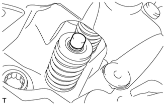
Remove the 16 valve adjusting shims from the cylinder head LH.
Tech Tips
Arrange the removed parts in such a way that they can be installed to their original locations.
-
-
REMOVE LH CYLINDER HEAD INTAKE VALVE
-
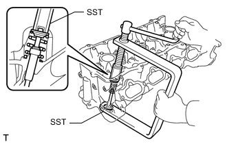
Using SST, compress the LH cylinder head intake valve and remove the 16 LH cylinder head valve spring retainer locks.
- SST
- 09202-70020 ( 09202-00010, 09202-01010, 09202-01020 )
-
Remove the 8 LH cylinder head valve spring retainers, 8 LH cylinder head intake valve compression springs and 8 LH cylinder head intake valves from the cylinder head LH.
Tech Tips
Arrange the removed parts in such a way that they can be installed to their original locations.
-
-
REMOVE LH CYLINDER HEAD EXHAUST VALVE
Tech Tips
Use the same procedure for the LH cylinder head exhaust valve and LH cylinder head intake valve.
-
REMOVE LH CYLINDER HEAD INTAKE VALVE STEM OIL SEAL
-
Remove the 8 LH cylinder head intake valve stem oil seals.
-
-
REMOVE LH CYLINDER HEAD EXHAUST VALVE STEM OIL SEAL
Tech Tips
Use the same procedure for the LH cylinder head exhaust valve stem oil seal and LH cylinder head intake valve stem oil seal.
-
REMOVE LH CYLINDER HEAD VALVE SPRING SEAT
-
Using compressed air and a magnet hand, remove the 16 LH cylinder head valve spring seats from the cylinder head LH by blowing air onto them.
Tech Tips
Arrange the removed parts in such a way that they can be installed to their original locations.
-
-
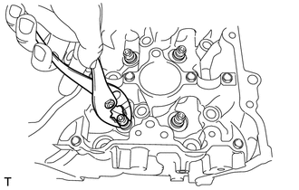
REMOVE NO. 1 STRAIGHT SCREW PLUG
Tech Tips
If coolant leaks from a No. 1 straight screw plug or the No. 1 straight screw plug is corroded, replace it.
-
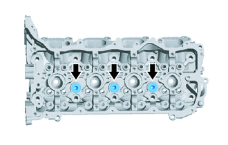
Using a 10 mm hexagon socket wrench, remove the 3 No. 1 straight screw plugs and 3 No. 2 water hole gaskets from the cylinder head LH.
-
-
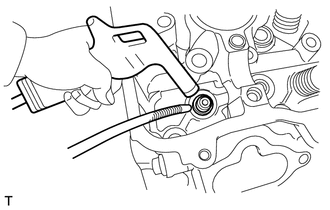
REMOVE NO. 2 STRAIGHT SCREW PLUG
Tech Tips
If coolant leaks from a No. 2 straight screw plug or the No. 2 straight screw plug is corroded, replace it.
-
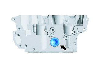
Using a 14 mm hexagon socket wrench, remove the No. 2 straight screw plug and No. 2 cylinder head screw plug gasket from the cylinder head LH.
-
-
REMOVE STUD BOLT
Tech Tips
If a stud bolt is deformed or the threads are damaged, replace it.
-
Using E6, E7 and E8 "TORX" socket wrenches, remove the stud bolts.
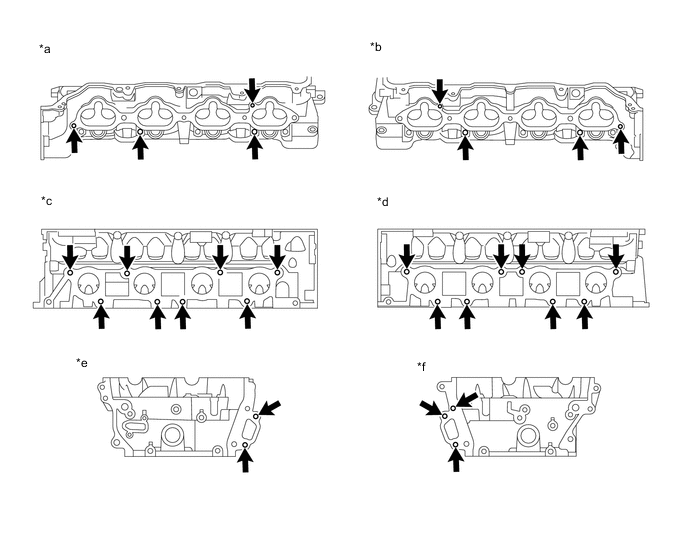
*a for Bank 2 Intake Side *b for Bank 1 Intake Side *c for Bank 2 Exhaust Side *d for Bank 1 Exhaust Side *e for Bank 2 Front Side *f for Bank 1 Front Side
-