ENGINE UNIT INSTALLATION

PROCEDURE
-
INSTALL NO. 3 V-BANK COVER BRACKET SUB-ASSEMBLY
-
Install the No. 3 V-bank cover bracket sub-assembly with the bolt.
- Torque:
- 10 N*m { 102 kgf*cm, 7 ft.*lbf }
-
-
INSTALL NO. 4 V-BANK COVER BRACKET SUB-ASSEMBLY
-
Install the No. 4 V-bank cover bracket sub-assembly with the nut.
- Torque:
- 10 N*m { 102 kgf*cm, 7 ft.*lbf }
-
-
INSTALL IGNITION COIL ASSEMBLY
-
INSTALL KNOCK SENSOR
-
INSTALL ENGINE COOLANT TEMPERATURE SENSOR
-
INSTALL NO. 2 WATER BY-PASS PIPE SUB-ASSEMBLY
-
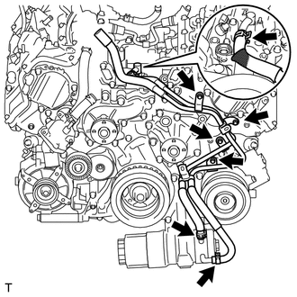
Install the No. 2 water by-pass pipe sub-assembly with the 4 bolts.
- Torque:
- 10 N*m { 102 kgf*cm, 7 ft.*lbf }
-
Connect the No. 2 water by-pass pipe sub-assembly to the oil cooler and heat exchanger assembly and slide the 3 clips to secure it.
-
-
INSTALL ENGINE OIL LEVEL SENSOR
-
INSTALL OIL TEMPERATURE SENSOR
-
INSTALL ENGINE OIL PRESSURE SWITCH ASSEMBLY
-
INSTALL WATER INLET HOUSING
-
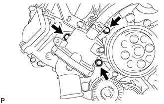
Install the water inlet housing and a new gasket with the 3 bolts.
- Torque:
- 21 N*m { 214 kgf*cm, 15 ft.*lbf }
-
Connect the water inlet hose to the water inlet housing and slide the clip to secure it.
-
-
INSTALL WATER PUMP PULLEY
-
INSTALL OIL PUMP DRIVE SHAFT PULLEY
-
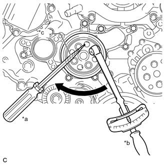
*a Hold *b Turn *c Protective Tape Temporarily install the pulley with the 4 bolts.
-
Using a screwdriver or an equivalent, hold the pulley and tighten the 4 bolts.
- Torque:
- 21 N*m { 214 kgf*cm, 15 ft.*lbf }
Tech Tips
Tape the screwdriver tip before use to avoid damage.
-
-
INSTALL NO. 2 IDLER PULLEY SUB-ASSEMBLY
-
Install the No. 2 idler pulley sub-assembly with the bolt.
- Torque:
- 43 N*m { 438 kgf*cm, 32 ft.*lbf }
-
-
INSTALL NO. 4 ENGINE COVER SUB-ASSEMBLY
-
Install the No. 4 engine cover sub-assembly.
-
-
INSTALL NO. 5 ENGINE WIRE
-
Install the No. 5 engine wire with the 2 bolts.
- Torque:
- 10 N*m { 102 kgf*cm, 7 ft.*lbf }
-
Connect the 4 knock sensor connectors.
-
-
INSTALL FUEL INJECTOR SEAL (for Direct Injection)
-
INSTALL DIRECT FUEL INJECTOR ASSEMBLY (for Direct Injection)
-
INSTALL FUEL DELIVERY PIPE LH (for Direct Injection)
-
INSTALL FUEL DELIVERY PIPE RH (for Direct Injection)
-
INSTALL CASE SEPARATOR
-
Install separator case to the cylinder head with the 4 bolts.
- Torque:
- 10 N*m { 102 kgf*cm, 7 ft.*lbf }
-
Connect the fuel pressure sensor connector.
-
-
INSTALL NO. 4 FUEL PIPE SUB-ASSEMBLY (for Direct Injection)
-
INSTALL NO. 2 ENGINE COVER SUB-ASSEMBLY LH
-
SET FUEL PUMP WITH SEAL SUB-ASSEMBLY (for Bank 1)
-
SET FUEL PUMP WITH SEAL SUB-ASSEMBLY (for Bank 2)
Tech Tips
Use the same procedure as for the bank 1 side.
-
TEMPORARILY INSTALL NO. 2 FUEL PIPE SUB-ASSEMBLY
-
TEMPORARILY INSTALL NO. 3 FUEL PIPE SUB-ASSEMBLY
-
INSTALL FUEL PUMP WITH SEAL SUB-ASSEMBLY (for Bank 1)
-
INSTALL FUEL PUMP WITH SEAL SUB-ASSEMBLY (for Bank 2)
-
INSTALL NO. 2 FUEL PIPE SUB-ASSEMBLY
-
INSTALL NO. 3 FUEL PIPE SUB-ASSEMBLY
-
INSTALL NO. 1 FUEL PIPE SUB-ASSEMBLY
-
INSTALL NO. 3 COVER SUB-ASSEMBLY
-
INSTALL NO. 1 ENGINE COVER SUB-ASSEMBLY
-
INSTALL INTAKE AIR SURGE TANK ASSEMBLY
-
CONNECT NO. 1 FUEL PIPE SUB-ASSEMBLY
-
INSTALL PORT FUEL INJECTOR ASSEMBLY (for Port Injection)
-
INSTALL INJECTOR VIBRATION INSULATOR (for Port Injection)
-
INSTALL NO. 1 DELIVERY PIPE SPACER (for Port Injection)
-
INSTALL FUEL DELIVERY PIPE SUB-ASSEMBLY (for Port Injection)
-
INSTALL NO. 2 FUEL DELIVERY PIPE SUB-ASSEMBLY (for Port Injection)
-
INSTALL FUEL TUBE SUB-ASSEMBLY (for Port Injection)
-
CONNECT VENTILATION HOSE
-
INSTALL PURGE VALVE (PURGE VSV)
-
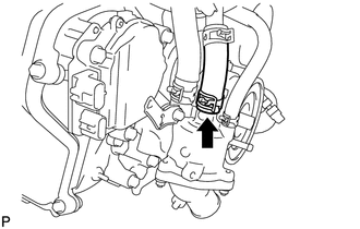
INSTALL WATER BY-PASS PIPE SUB-ASSEMBLY
-
Install the water by-pass pipe sub-assembly to the intake air surge tank assembly with the 2 bolts.
- Torque:
- 10 N*m { 102 kgf*cm, 7 ft.*lbf }
-
Connect the No. 5 water by-pass hose to the water by-pass pipe sub-assembly and slide the clip to secure it.
-
Connect the water by-pass hose to the water by-pass pipe sub-assembly and slide the clip to secure it.
-
Connect the No. 3 water by-pass hose to the water by-pass pipe sub-assembly and slide the clip to secure it.
-
-
INSTALL INJECTOR DRIVER BRACKET
-
INSTALL INJECTOR DRIVER
-
INSTALL THROTTLE BODY WITH MOTOR ASSEMBLY
-
INSTALL TRANSMISSION BREATHER ASSEMBLY
-
INSTALL WIRE HARNESS CLAMP BRACKET
-
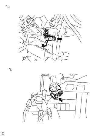
*a for LH Side *b for RH Side Install the 2 wire harness clamp brackets with the 2 bolts.
- Torque:
- for LH side
- 21 N*m { 214 kgf*cm, 15 ft.*lbf }
- for RH side
- 29 N*m { 296 kgf*cm, 21 ft.*lbf }
-
-
INSTALL FRONT NO. 1 ENGINE MOUNTING BRACKET LH
-
Install the front No. 1 engine mounting bracket LH with the 4 bolts.
- Torque:
- 35 N*m { 357 kgf*cm, 26 ft.*lbf }
-
-
INSTALL FRONT NO. 1 ENGINE MOUNTING BRACKET RH
-
Install the front No. 1 engine mounting bracket RH with the 4 bolts.
- Torque:
- 35 N*m { 357 kgf*cm, 26 ft.*lbf }
-
-
INSTALL ENGINE WIRE
-
Install the engine wire to the engine assembly.
-
-
INSTALL NO. 1 ENGINE HANGER
-
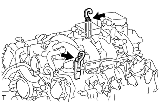
Install the 2 No. 1 engine hangers with the 2 bolts as shown in the illustration.
Part No. Item Part No. No. 1 Engine Hanger 12081-38040 Bolt 90119-14120 - Torque:
- 43 N*m { 438 kgf*cm, 32 ft.*lbf }
-
-
REMOVE ENGINE FROM ENGINE STAND
-
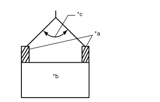
*a No. 1 Engine Hanger *b Engine Assembly *c 50° or Less Attach an engine sling device and hang the engine assembly with a chain block.
Tech Tips
When hanging the engine assembly, make sure to hang the engine assembly with the chain at an angle of 50° or less. Otherwise, the engine assembly or engine hangers may be damaged.
-
Remove the bolts and engine assembly from the engine stand.
-