ENGINE UNIT REASSEMBLY

CAUTION / NOTICE / HINT
Tech Tips
Perform "Inspection After Repair" after removal and installation of the camshaft timing control motor with EDU assembly or the camshaft timing gear assembly.
-
w/ Canister Pump Module:
-
w/o Canister Pump Module:
PROCEDURE
-
REPLACE TIMING CHAIN COVER STRAIGHT PIN
Tech Tips
It is not necessary to remove the straight pins unless they are being replaced.
-
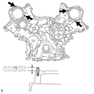
*1 5.5 to 6.5 mm Remove the 4 timing chain cover straight pins.
-
Using a plastic-faced hammer, tap in new timing chain cover straight pins to the timing chain cover assembly.
Standard Protrusion 5.5 to 6.5 mm (0.217 to 0.256 in.)
-
-
REPLACE RING PIN
Tech Tips
It is not necessary to remove the ring pins unless they are being replaced.
-
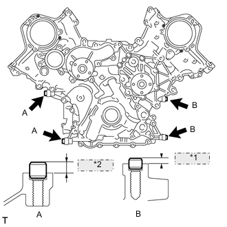
*1 3.6 to 4.6 mm *2 7.5 to 8.5 mm Remove the 4 ring pins.
-
Using a plastic-faced hammer, tap in new ring pins to the timing chain cover assembly.
Standard Protrusion Ring Pin A 7.5 to 8.5 mm (0.295 to 0.335 in.) Ring Pin B 3.6 to 4.6 mm (0.142 to 0.181 in.)
-
-
REPLACE STUD BOLT
Tech Tips
If a stud bolt is deformed or its threads are damaged, replace it.
-
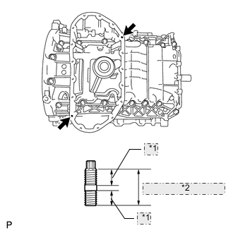
*1 9.0 mm (0.354 in.) *2 19.0 mm (0.748 in.) Using an E6 "TORX" socket wrench, install the 2 stud bolts as shown in the illustration.
- Torque:
- 5.0 N*m { 51 kgf*cm, 44 in.*lbf }
-
-
INSTALL OIL DRAIN PIPE SUB-ASSEMBLY
-
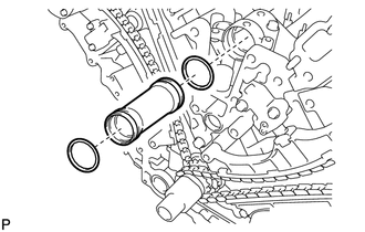
Apply a light coat of engine oil to a new O-ring.
-
Install the O-ring to the oil drain pipe sub-assembly.
-
Install the oil drain pipe sub-assembly with the bolt.
- Torque:
- 10 N*m { 102 kgf*cm, 7 ft.*lbf }
-
-
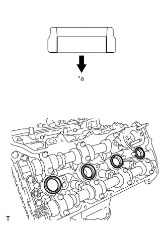
INSTALL ENGINE REAR OIL SEAL
-
Apply MP grease to the lip of a new engine rear oil seal.
-
Place the engine rear oil seal retainer on wooden blocks.
-
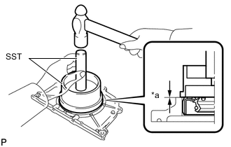
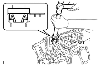
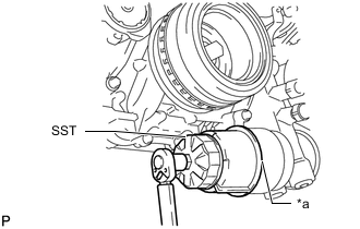
*a Standard Protrusion Height Using SST, tap in the engine rear oil seal until its surface is flush with the engine rear oil seal retainer edge.
- SST
- 09223-15030
- 09950-70010 ( 09951-07100 )
Standard Protrusion Height -1.0 to 0 mm (-0.0394 to 0 in.) Note
-
Keep the lip free from foreign matter.
-
Do not tap in the engine rear oil seal at an angle.
-
-
INSTALL ENGINE REAR OIL SEAL RETAINER
-
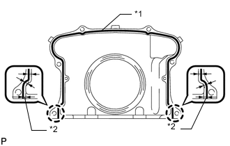
*1 2.0 to 3.0 mm *2 3.5 mm Apply seal packing in a continuous line as shown in the illustration.
Seal Packing Toyota Genuine Seal Packing Black, Three Bond 1207B or equivalent Seal Diameter 2.0 to 3.0 mm (0.0787 to 0.118 in.) Application Position from Inside Edge of Retainer 3.5 mm (0.138 in.) Note
-
Remove any oil from the contact surfaces.
-
Install the engine rear oil seal retainer within 3 minutes and tighten the bolts within 15 minutes of applying seal packing.
-
-
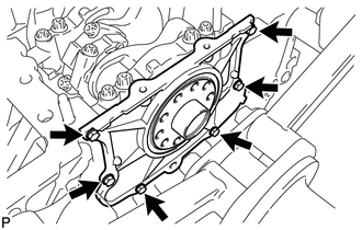
Install the engine rear oil seal retainer with the 6 bolts.
- Torque:
- 10 N*m { 102 kgf*cm, 7 ft.*lbf }
-
-
INSTALL OIL STRAINER SUB-ASSEMBLY
-
Apply a light coat of engine oil to a new O-ring.
-
Install the O-ring to the oil strainer sub-assembly.
-
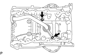
Install the oil strainer sub-assembly with the 2 bolts.
- Torque:
- 21 N*m { 214 kgf*cm, 15 ft.*lbf }
Note
Make sure that the O-ring is not twisted or damaged.
-
-
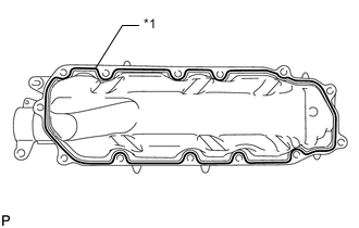
INSTALL NO. 1 OIL PAN BAFFLE PLATE
-
Install the No. 1 oil pan baffle plate with the 8 bolts.
- Torque:
- 10 N*m { 102 kgf*cm, 7 ft.*lbf }
-
-
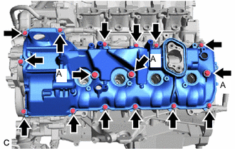
INSTALL OIL PAN SUB-ASSEMBLY
-
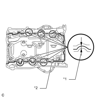
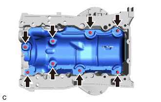
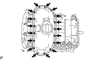
*1 6.0 mm *2 3.0 to 4.0 mm Apply seal packing in a continuous line as shown in the illustration.
Seal Packing Toyota Genuine Seal Packing Black, Three Bond 1207B or equivalent Standard Seal Diameter 3.0 to 4.0 mm (0.118 to 0.157 in.) Application Position From Inside Edge of Oil Pan 6.0 mm (0.236 in.) Note
-
Check and clean the bolts and bolt holes.
-
Remove any oil from the contact surfaces.
-
Install the oil pan sub-assembly within 3 minutes and tighten the bolts and nuts within 15 minutes of applying seal packing.
-
Do not add engine oil for at least 2 hours after installation.
-
Do not start the engine for at least 2 hours after installation.
-
-
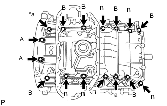
*a Nut Install the oil pan sub-assembly with the 14 bolts and 2 nuts.
- Torque:
- Bolt (A)
- 10 N*m { 102 kgf*cm, 7 ft.*lbf }
- Bolt (B)
- 35 N*m { 357 kgf*cm, 26 ft.*lbf }
- Nut
- 35 N*m { 357 kgf*cm, 26 ft.*lbf }
-
-
INSTALL NO. 2 OIL PAN SUB-ASSEMBLY
-
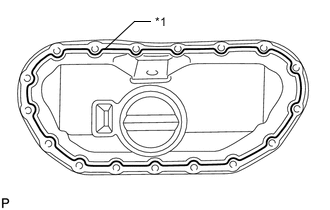
*1 3.0 to 4.0 mm Apply seal packing in a continuous line as shown in the illustration.
Seal Packing Toyota Genuine Seal Packing Black, Three Bond 1207B or equivalent Standard Seal Diameter 3.0 to 4.0 mm (0.118 to 0.157 in.) Note
-
Check and clean the bolts and bolt holes.
-
Remove any oil from the contact surfaces.
-
Install the No. 2 oil pan sub-assembly within 3 minutes and tighten the bolts and nuts within 15 minutes of applying seal packing.
-
Do not start the engine for at least 2 hours after installation.
-
Do not add engine oil for at least 2 hours after installation.
-
-
*a Nut Install the No. 2 oil pan sub-assembly with the 15 bolts and 2 nuts.
- Torque:
- 10 N*m { 102 kgf*cm, 7 ft.*lbf }
-
-
INSTALL VENTILATION PIPE GASKET
-
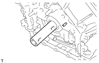
Using SST, evenly tap in a new ventilation pipe gasket until its surface is flush with the edge of the ventilation pipe gasket.
- SST
- 09950-60010 ( 09951-00360 )
- 09950-70010 ( 09951-07100 )
Tech Tips
-
Do not tap in the ventilation pipe gasket at an angle.
-
Do not tap in the ventilation pipe gasket excessively.
-
-
INSTALL HEAT EXCHANGER ASSEMBLY
-
*1 3.0 to 4.0 mm Apply seal packing in a continuous line as shown in the illustration.
Seal Packing Toyota Genuine Seal Packing 1282B, Three Bond 1282B or equivalent Standard Seal Diameter 3.0 to 4.0 mm (0.118 to 0.157 in.) Note
Remove any oil from the contact surfaces.
-
*a Nut Install the heat exchanger assembly with the 11 bolts and 2 nuts.
- Torque:
- 21 N*m { 214 kgf*cm, 15 ft.*lbf }
Note
-
Install the heat exchanger assembly within 3 minutes and tighten the bolts and nuts within 15 minutes of applying seal packing.
-
Do not start the engine for at least 2 hours after installing the cover.
-
Install the bolt.
- Torque:
- 10 N*m { 102 kgf*cm, 7 ft.*lbf }
-
-
INSTALL CYLINDER BLOCK WATER JACKET SPACER
-
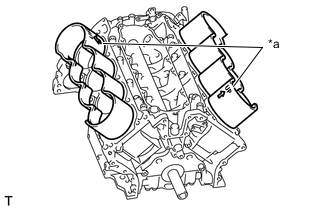
*a UP Mark Install the 2 cylinder block water jacket spacers to the cylinder block sub-assembly as shown in the illustration.
Tech Tips
-
Face the cutouts away from the center of the engine.
-
Face each UP mark as shown in the illustration.
-
-
-
INSTALL NO. 2 CYLINDER HEAD GASKET
-
INSTALL CYLINDER HEAD LH
-
INSTALL CYLINDER HEAD GASKET
-
INSTALL CYLINDER HEAD SUB-ASSEMBLY
-
INSTALL CYLINDER HEAD VALVE ROCKER ARM PIVOT RH
-
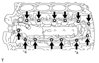
Install the 16 cylinder head valve rocker arm pivots RH to the cylinder head assembly.
- Torque:
- 22.5 N*m { 229 kgf*cm, 17 ft.*lbf }
-
-
INSTALL CYLINDER HEAD VALVE ROCKER ARM PIVOT LH
-
Install the 16 cylinder head valve rocker arm pivots LH to the cylinder head LH.
- Torque:
- 22.5 N*m { 229 kgf*cm, 17 ft.*lbf }
-
-
INSTALL NO. 1 VALVE ROCKER ARM SUB-ASSEMBLY
-
Apply engine oil to the cylinder head valve rocker arm pivot and valve adjusting shim.
-
Install the 32 No. 1 valve rocker arm sub-assemblies to the cylinder head LH and cylinder head sub-assembly.
-
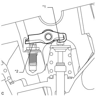
*1 Valve Adjusting Shim *2 Cylinder Head Valve Rocker Arm Pivot Make sure that the 32 No. 1 valve rocker arm sub-assemblies are installed as shown in the illustration.
-
-
INSTALL NO. 3 CAMSHAFT SUB-ASSEMBLY
-
INSTALL NO. 4 CAMSHAFT SUB-ASSEMBLY
-
INSTALL CAMSHAFT BEARING CAP (for Bank 1)
-
INSTALL CAMSHAFT
-
INSTALL NO. 2 CAMSHAFT
-
INSTALL CAMSHAFT BEARING CAP (for Bank 2)
-
INSTALL CRANKSHAFT TIMING GEAR KEY
-
Install the 2 crankshaft timing gear keys.
-
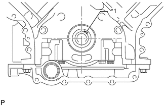
*1 Crankshaft Timing Gear Key Temporarily install the crankshaft pulley set bolt, and set the crankshaft timing gear key in the position shown in the illustration.
-
Remove the crankshaft pulley set bolt.
-
-
INSTALL NO. 2 CHAIN TENSIONER ASSEMBLY
-
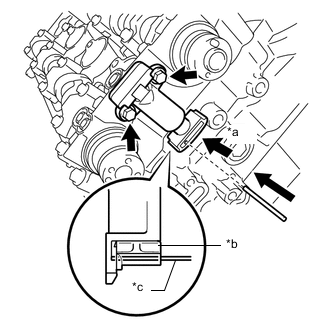
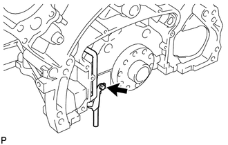
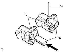
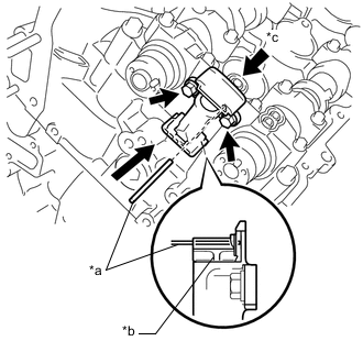
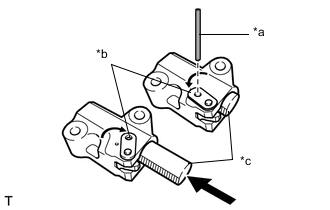
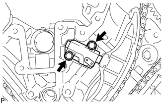
*a Push *b Plunger *c Pin Install the No. 2 chain tensioner assembly with the 2 bolts.
- Torque:
- 10 N*m { 102 kgf*cm, 7 ft.*lbf }
-
While pushing down the No. 2 chain tensioner assembly, insert a pin of 1.0 mm (0.0394 in.) diameter into the hole to secure it in place.
-
-
INSTALL CHAIN SUB-ASSEMBLY (for Bank 2)
Tech Tips
The crankshaft timing gear, camshaft timing gear assembly and camshaft timing exhaust gear will be installed with the chain sub-assembly and No. 2 chain sub-assembly attached to the gears.
-
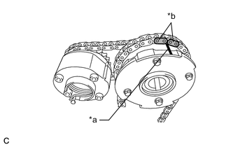
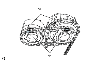
*a Timing Mark *b Mark Plate Align the mark plates (orange) of the chain sub-assembly with the timing mark of the camshaft gear, and attach the chain to the gear as shown in the illustration.
-
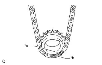
*a Timing Mark *b Mark Plate Align the mark plate (orange) of the chain sub-assembly with the timing mark of the crankshaft gear, and attach the chain to the gear as shown in the illustration.
-
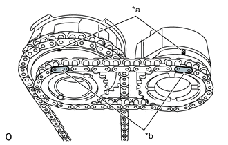
*a Timing Mark *b Mark Plate Align the mark plates (yellow) of the No. 2 chain sub-assembly with the timing marks of the camshaft timing gear assembly and camshaft timing exhaust gear assembly, and attach the No. 2 chain sub-assembly to the gears as shown in the illustration.
-
Install the crankshaft timing gear to the crankshaft.
-
Align and fit the knock pin of the camshaft to the pin hole of the camshaft timing gear assembly.
-
Using a wrench, hold the hexagonal portion of the No. 2 camshaft, align and fit the knock pin of the No. 2 camshaft to the pin hole of the camshaft timing exhaust gear.
Note
Because the timing mark positions of the gears may shift due to looseness of the chain sub-assembly, using a wrench, hold the hexagonal portion of the camshaft to hold the No. 3 camshaft sub-assembly in place until the No. 1 chain tensioner assembly is installed.
-
Remove the pin from the No. 2 chain tensioner assembly.
-
-
INSTALL NO. 1 CHAIN VIBRATION DAMPER (for Bank 2)
-
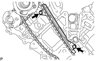
Install the No. 1 chain vibration damper with the 2 bolts.
- Torque:
- 21 N*m { 214 kgf*cm, 15 ft.*lbf }
-
-
INSTALL CHAIN TENSIONER SLIPPER (for Bank 2)
-
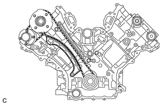
Install the chain tensioner slipper.
Tech Tips
If it is difficult to install the chain tensioner slipper due to the tension of the chain sub-assembly, using a wrench, hold the hexagonal portion of the camshaft to loosen the chain sub-assembly, and then install the chain tensioner slipper.
-
-
INSTALL NO. 1 CHAIN TENSIONER ASSEMBLY (for Bank 2)
-
*a Pin *b Stopper Plate *c Plunger Turn the stopper plate clockwise to release the lock, and fully push the plunger into the No. 1 chain tensioner assembly.
-
Turn the stopper plate counterclockwise to set the lock, and insert a pin of 1.0 mm (0.0394 in.) diameter into the stopper plate hole.
-
Install the No. 1 chain tensioner assembly with the 2 bolts.
- Torque:
- 10 N*m { 102 kgf*cm, 7 ft.*lbf }
-
Remove the pin from the No. 1 chain tensioner assembly.
-
-
INSTALL NO. 3 CHAIN TENSIONER ASSEMBLY
-
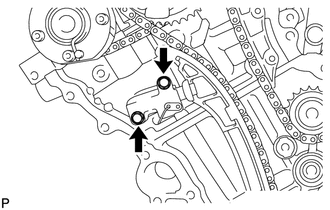
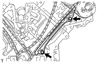
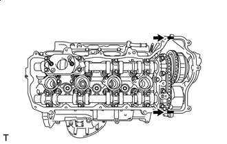
*a Pin *b Plunger *c Push Install the No. 3 chain tensioner assembly with the 2 bolts.
- Torque:
- 10 N*m { 102 kgf*cm, 7 ft.*lbf }
-
While fully pushing the plunger into the No. 3 chain tensioner assembly, insert a pin of 1.0 mm (0.0394 in.) diameter into the hole to secure it in place.
-
-
INSTALL CHAIN SUB-ASSEMBLY (for Bank 1)
Tech Tips
The crankshaft timing sprocket LH, camshaft timing gear assembly and camshaft timing exhaust gear will be installed with the chain sub-assembly and No. 2 chain sub-assembly attached to the gears.
-
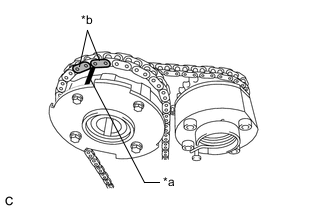
*a Timing Mark *b Mark Plate Align the mark plates (orange) of the chain sub-assembly with the timing mark of the camshaft timing gear, and attach the chain to the gear as shown in the illustration.
-
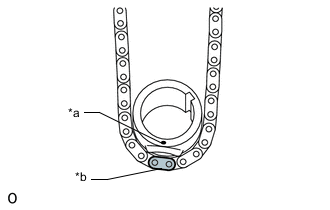
*a Timing Mark *b Mark Plate Align the mark plate (orange) of the chain sub-assembly with the timing mark of the crankshaft timing sprocket, and attach the chain to the gear as shown in the illustration.
-
*a Timing Mark *b Mark Plate Align the mark plates (yellow) of the No. 2 chain sub-assembly with the timing marks of the camshaft timing gear assembly and camshaft timing exhaust gear, and attach the No. 2 chain sub-assembly to the gears as shown in the illustration.
-
Install the crankshaft timing sprocket LH to the crankshaft.
-
Align and fit the knock pin of the No. 3 camshaft sub-assembly to the pin hole of the camshaft timing gear assembly.
-
Using a wrench, hold the hexagonal portion of the No. 4 camshaft sub-assembly, align and fit the knock pin of the No. 4 camshaft sub-assembly with the pin hole of the camshaft timing exhaust gear.
Note
Because the timing marks of the gears may shift due to looseness of the chain sub-assembly, using a wrench, hold the hexagonal portion of the camshaft to hold the No. 3 camshaft sub-assembly in place until the No. 1 chain tensioner assembly is installed.
-
Remove the pin from the No. 3 chain tensioner assembly.
-
-
INSTALL NO. 1 CHAIN VIBRATION DAMPER (for Bank 1)
-
Install the No. 1 chain vibration damper with the 2 bolts.
- Torque:
- 21 N*m { 214 kgf*cm, 15 ft.*lbf }
-
Remove the pin from the No. 1 chain tensioner assembly.
-
-
INSTALL CHAIN TENSIONER SLIPPER (for Bank 1)
-
Install the chain tensioner slipper.
Tech Tips
If you cannot install the chain tensioner slipper due to the tension of the chain sub-assembly, using a wrench, hold the hexagonal portion of the camshaft to loosen the chain sub-assembly and install the chain tensioner slipper.
-
-
INSTALL NO. 1 CHAIN TENSIONER ASSEMBLY (for Bank 1)
-
*a Pin *b Stopper Plate *c Plunger Turn the stopper plate clockwise to release the lock, and fully push the plunger into the No. 1 chain tensioner assembly.
-
Turn the stopper plate counterclockwise to set the lock, and insert a pin of 1.0 mm (0.0394v in.) diameter into the stopper plate hole.
-
Install a new chain tensioner gasket and the No. 1 chain tensioner assembly with the 2 bolts.
- Torque:
- 10 N*m { 102 kgf*cm, 7 ft.*lbf }
-
Remove the pin from the No. 1 chain tensioner assembly.
-
-
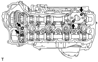
TIGHTEN CAMSHAFT TIMING GEAR ASSEMBLY (for Bank 1)
-
Using a wrench, hold the hexagonal portion of the No. 3 camshaft sub-assembly.
-
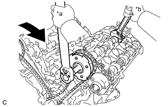
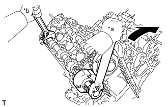
*a Turn *b Hold Using a 12 mm hexagon socket wrench, tighten a new bolt of the camshaft timing gear assembly.
- Torque:
- 79 N*m { 806 kgf*cm, 58 ft.*lbf }
-
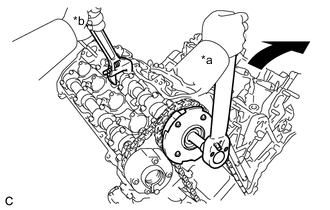
*a Turn *b Hold Using a wrench to hold the hexagonal portion of the No. 4 camshaft sub-assembly, tighten the bolt of the camshaft timing exhaust gear.
- Torque:
- 100 N*m { 1020 kgf*cm, 74 ft.*lbf }
-
-
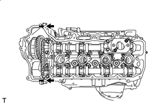
TIGHTEN CAMSHAFT TIMING GEAR ASSEMBLY (for Bank 2)
-
Using a wrench, hold the hexagonal portion of the camshaft.
-
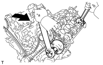
*a Turn *b Hold Using a 12 mm hexagon socket wrench, tighten a new bolt of the camshaft timing gear assembly.
- Torque:
- 79 N*m { 806 kgf*cm, 58 ft.*lbf }
-
*a Turn *b Hold Using a wrench to hold the hexagonal portion of the No. 2 camshaft, tighten the bolt of the camshaft timing exhaust gear.
- Torque:
- 100 N*m { 1020 kgf*cm, 74 ft.*lbf }
-
-
INSPECT NO. 1 CYLINDER TO TDC / COMPRESSION
-
INSPECT VALVE CLEARANCE
-
ADJUST VALVE CLEARANCE
-
INSTALL OIL REFLECTOR PLATE LH
-
Install the oil reflector plate LH to the cylinder head LH with the 2 bolts.
- Torque:
- 10 N*m { 102 kgf*cm, 7 ft.*lbf }
-
-
INSTALL OIL REFLECTOR PLATE RH
-
Install the oil reflector plate RH to the cylinder head sub-assembly with the 2 bolts.
- Torque:
- 10 N*m { 102 kgf*cm, 7 ft.*lbf }
-
-
INSTALL SCAVENGING PUMP ASSEMBLY
-
INSTALL NO. 3 OIL PIPE
-
INSTALL NO. 2 OIL PIPE
-
INSTALL NO. 1 OIL PIPE
-
INSTALL INLET WATER PIPE
-
Apply soapy water to 2 new O-rings and install them to the inlet water pipe.
-
Install the inlet pipe to the heat exchanger assembly.
-
-
INSTALL TIMING CHAIN COVER ASSEMBLY
-
INSTALL TIMING GEAR CASE OR TIMING CHAIN CASE OIL SEAL
-
INSTALL ENGINE WATER PUMP ASSEMBLY
-
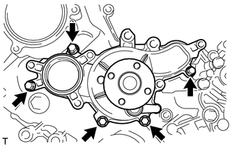
Install a new water pump gasket and the engine water pump assembly to the timing chain cover assembly with the 5 bolts.
- Torque:
- 20 N*m { 204 kgf*cm, 15 ft.*lbf }
-
-
INSTALL V-RIBBED BELT TENSIONER ASSEMBLY
-
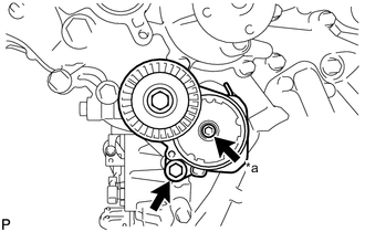
*a 6 mm Hexagon Bolt Install the V-ribbed belt tensioner assembly with the bolt and 6 mm hexagon bolt.
- Torque:
- 23 N*m { 235 kgf*cm, 17 ft.*lbf }
-
-
INSTALL OIL CONTROL VALVE FILTER LH
-
Install the oil control valve filter LH to the cylinder head cover spacer LH.
-
Install a new gasket and the cylinder head cover spacer LH with the 2 bolts.
- Torque:
- 10 N*m { 102 kgf*cm, 7 ft.*lbf }
-
-
INSTALL OIL CONTROL VALVE FILTER RH
-
Install the oil control valve filter RH to the cylinder head cover spacer RH.
-
Install a new gasket and the cylinder head cover spacer RH with the 2 bolts.
- Torque:
- 10 N*m { 102 kgf*cm, 7 ft.*lbf }
-
-
INSTALL SPARK PLUG TUBE GASKET
-
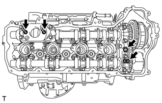
*a Bottom Install 8 new spark plug tube gaskets to the cylinder head LH and cylinder head sub-assembly.
Note
-
Make sure to install the spark plug tube gaskets in the correct orientation.
-
Push in each spark plug tube gasket until its bottom surface contacts the cylinder head.
-
-
-
INSTALL CYLINDER HEAD COVER SUB-ASSEMBLY LH
-
Install 2 new oil hole gaskets and 2 new O-rings to the camshaft bearing caps.
-
Install a new cylinder head cover gasket LH to the cylinder head cover sub-assembly LH.
Note
Remove any oil from the contact surfaces.
-

Seal Packing Apply seal packing as shown in the illustration.
Seal Packing Toyota Genuine Seal Packing Black, Three Bond 1207B or equivalent Note
-
Remove any oil from the contact surfaces.
-
Install the cylinder head cover sub-assembly LH within 3 minutes and tighten the bolts within 15 minutes of applying seal packing.
-
Do not start the engine for at least 2 hours after installing the cylinder head cover sub-assembly LH.
-
-
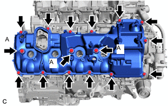
Install the cylinder head cover sub-assembly LH with 3 new seal washers and the 16 bolts.
- Torque:
- Bolt (A)
- 21 N*m { 214 kgf*cm, 15 ft.*lbf }
- except Bolt (A)
- 12 N*m { 122 kgf*cm, 9 ft.*lbf }
-
Install a new fuel pump spacer gasket.
-
-
INSTALL CYLINDER HEAD COVER SUB-ASSEMBLY
-
Install 2 new oil hole gaskets and 2 new O-rings to the camshaft bearing caps.
-
Install a new cylinder head cover gasket to the cylinder head cover sub-assembly.
Note
Remove any oil from the contact surfaces.
-
Seal Packing Apply seal packing as shown in the illustration.
Seal Packing Toyota Genuine Seal Packing Black, Three Bond 1207B or equivalent Note
-
Remove any oil from the contact surfaces.
-
Install the cylinder head cover sub-assembly within 3 minutes and tighten the bolts within 15 minutes of applying seal packing.
-
Do not start the engine for at least 2 hours after installing the cylinder head cover sub-assembly.
-
-
Install the cylinder head cover sub-assembly with 3 new seal washers and the 16 bolts.
- Torque:
- Bolt (A)
- 21 N*m { 214 kgf*cm, 15 ft.*lbf }
- except Bolt (A)
- 12 N*m { 122 kgf*cm, 9 ft.*lbf }
-
Install a new fuel pump spacer gasket.
-
-
INSTALL NO. 1 V-BANK COVER BRACKET (for Bank 1)
-
Install the No. 1 V-bank cover bracket to the cylinder head cover sub-assembly LH.
- Torque:
- 10 N*m { 102 kgf*cm, 7 ft.*lbf }
-
-
INSTALL NO. 1 V-BANK COVER BRACKET (for Bank 2)
-
Install the No. 1 V-bank cover bracket to the cylinder head cover sub-assembly.
- Torque:
- 10 N*m { 102 kgf*cm, 7 ft.*lbf }
-
-
INSTALL CRANKSHAFT PULLEY
-
INSTALL OIL FILTER BRACKET
-
Install 2 new gaskets to the timing chain cover assembly.
-
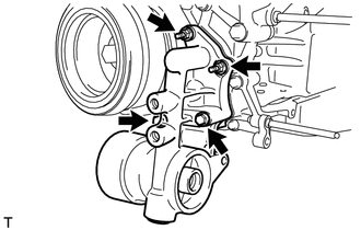
Install the oil filter bracket with the 2 bolts and 2 nuts.
- Torque:
- 21 N*m { 214 kgf*cm, 15 ft.*lbf }
-
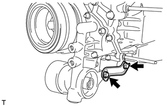
Install the oil filter bracket stay with the 2 bolts.
- Torque:
- 21 N*m { 214 kgf*cm, 15 ft.*lbf }
-
-
INSTALL OIL THERMOSTAT HOUSING ASSEMBLY
-
INSTALL OIL FILTER CAP ASSEMBLY
-
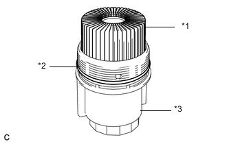
*1 Oil Filter Element *2 O-Ring *3 Oil Filter Cap Assembly Clean the inside of the oil filter cap assembly, the threads and O-ring groove.
-
Apply a light coat of engine oil to a new O-ring and install it to the oil filter cap assembly.
-
Install a new oil filter element to the oil filter cap assembly.
-
Remove any dirt and foreign matter from the installation surface of the oil filter bracket.
-
Apply a light coat of engine oil to the O-ring again and install the oil filter cap assembly.
-
*a No clearance Using SST, tighten the oil filter cap assembly.
- SST
- 09228-06501
- Torque:
- 25 N*m { 255 kgf*cm, 18 ft.*lbf }
Note
-
Make sure that the oil filter cap assembly is installed securely as shown in the illustration.
-
Make sure that the O-ring does not get caught between the parts.
-
-
INSTALL CYLINDER BLOCK WATER DRAIN COCK SUB-ASSEMBLY
-
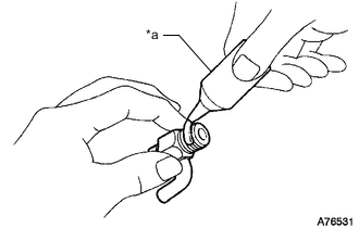
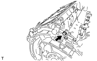
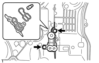
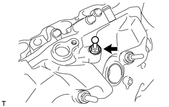
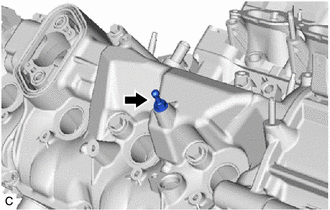
*a Adhesive Apply adhesive to 2 or 3 threads of the cylinder block water drain cock sub-assembly.
Adhesive Toyota Genuine Adhesive 1344, Three Bond 1344 or equivalent Note
To prevent contamination by foreign matter, install immediately after applying adhesive.
-
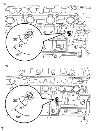
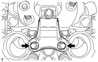
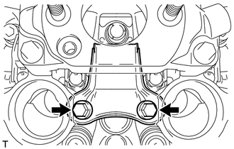
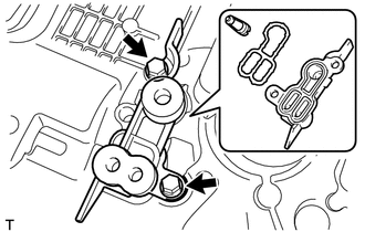
*a for Bank 1 *b for Bank 2 Install each cylinder block water drain cock sub-assembly to the cylinder block sub-assembly as shown in the illustration.
- Torque:
- 30 N*m { 306 kgf*cm, 22 ft.*lbf }
Note
-
Do not rotate the cylinder block water drain cock sub-assembly more than 1 revolution (360°) after tightening to the specified torque.
-
Do not loosen the cylinder block water drain cock sub-assembly to adjust it. If an adjustment is necessary, remove the cylinder block water drain cock sub-assembly and reinstall it.
-
Do not add coolant for at least 1 hour after installation.
-
Install the cylinder block water drain cock plug to each cylinder block water drain cock sub-assembly.
- Torque:
- 12.7 N*m { 130 kgf*cm, 9 ft.*lbf }
-
-
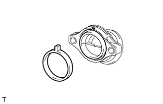
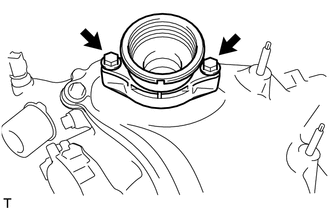
INSTALL FRONT WATER BY-PASS JOINT
-
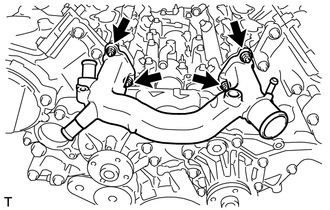
Install the front water by-pass joint and 2 new gaskets with the 4 nuts.
- Torque:
- 21 N*m { 214 kgf*cm, 15 ft.*lbf }
-
-
INSTALL CAMSHAFT TIMING CONTROL MOTOR WITH EDU ASSEMBLY LH
-
INSTALL CAMSHAFT TIMING CONTROL MOTOR WITH EDU ASSEMBLY RH
-
INSTALL CAMSHAFT TIMING OIL CONTROL VALVE ASSEMBLY LH
-
INSTALL CAMSHAFT TIMING OIL CONTROL VALVE ASSEMBLY RH
-
INSTALL CRANKSHAFT POSITION SENSOR
-
INSTALL CAMSHAFT POSITION SENSOR
-
INSTALL VVT SENSOR (for Intake Side of Bank 1)
-
INSTALL VVT SENSOR (for Intake Side of Bank 2)
-
INSTALL VVT SENSOR (for Exhaust Side of Bank 1)
-
INSTALL VVT SENSOR (for Exhaust Side of Bank 2)
-
INSTALL OIL PAN DRAIN PLUG
-
Install the oil pan drain plug and gasket to the No. 2 oil pan sub-assembly.
- Torque:
- 40 N*m { 408 kgf*cm, 30 ft.*lbf }
-
-
INSTALL SPARK PLUG
-
INSTALL OIL FILLER CAP HOUSING
-
Align the protrusion of a new oil filler cap housing gasket with the cutout of the oil filler cap housing, and install the oil filler cap housing gasket to the oil filler cap housing.
-
Install the oil filler cap housing with the 2 bolts.
- Torque:
- 10 N*m { 102 kgf*cm, 7 ft.*lbf }
-
-
INSTALL OIL FILTER CAP SUB-ASSEMBLY
-
Install a new oil filler cap gasket to the oil filler cap sub-assembly.
-
Install the oil filler cap sub-assembly to the oil filler cap housing.
-