ENGINE UNIT INSPECTION

PROCEDURE
-
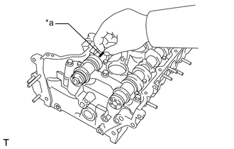
INSPECT NO. 1 VALVE ROCKER ARM SUB-ASSEMBLY
-
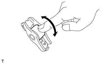
Turn the roller by hand to check that it turns smoothly.
If the roller does not turn smoothly, replace the No. 1 valve rocker arm sub-assembly.
-
-
INSPECT CAMSHAFT
-
Inspect the camshaft for runout.
-
Place the camshaft on V-blocks.
-
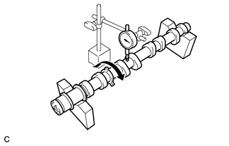
Using a dial indicator, measure the runout at the center journal.
Maximum Runout 0.04 mm (0.00157 in.) If the runout is more than the maximum, replace the camshaft.
-
-
Using a micrometer, measure the cam lobe height.
Standard Cam Lobe Height Item Specified Condition Intake 45.517 to 45.617 mm (1.79 to 1.80 in.) Exhaust 44.627 to 44.702 mm (1.76 to 1.76 in.) Minimum Cam Lobe Height Item Specified Condition Intake 44.903 mm (1.77 in.) Exhaust 44.526 mm (1.75 in.) If the cam lobe height is less than the minimum, replace the camshaft.
Check the oil clearance after replacing the camshaft.
-
Using a micrometer, measure the journal diameter.
Standard Journal Diameter Item Specified Condition No. 1 journal 29.956 to 29.970 mm (1.17937 to 1.17992 in.) Other journals 25.959 to 25.975 mm (1.02201 to 1.02264 in.) If the journal diameter is not as specified, check the oil clearance.
-
-
INSPECT CAMSHAFT OIL CLEARANCE (for Bank 1)
-
Clean the camshaft bearing caps, camshaft housing LH and camshaft journals.
-
Place the camshafts on the camshaft housing LH.
-
*a Plastigage Lay a strip of Plastigage across each camshaft journal.
-
Install the camshaft bearing caps.
Note
Do not turn the camshafts.
-
Remove the camshaft bearing caps.
-
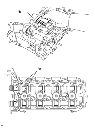
*a No. 1 Journal *b Plastigage Measure the Plastigage at its widest point.
Standard Oil Clearance Item Specified Condition No. 1 journal 0.030 to 0.069 mm (0.00118 to 0.00272 in.) Other journal 0.025 to 0.062 mm (0.000984 to 0.00244 in.) Maximum Oil Clearance Item Specified Condition No. 1 journal 0.09 mm (0.00354 in.) Other journal 0.09 mm (0.00354 in.) If the oil clearance is more than the maximum, replace the camshaft and measure the oil clearance again.
If the oil clearance is still more than the maximum even after replacing the camshaft with a new one, replace the cylinder head LH.
-
-
INSPECT CAMSHAFT OIL CLEARANCE (for Bank 2)
-
Clean the camshaft bearing caps, camshaft housing RH and camshaft journals.
-
Place the camshafts on the camshaft housing RH.
-
*a Plastigage Lay a strip of Plastigage across each camshaft journal.
-
Install the camshaft bearing caps.
Note
Do not turn the camshafts.
-
Remove the camshaft bearing caps.
-
*a No. 1 Journal *b Plastigage Measure the Plastigage at its widest point.
Standard Oil Clearance Item Specified Condition No. 1 journal 0.030 to 0.069 mm (0.00118 to 0.00272 in.) Other journal 0.025 to 0.062 mm (0.000984 to 0.00244 in.) Maximum Oil Clearance Item Specified Condition No. 1 journal 0.09 mm (0.00354 in.) Other journal 0.09 mm (0.00354 in.) If the oil clearance is more than the maximum, replace the camshaft and measure the oil clearance again.
If the oil clearance is still more than the maximum even after replacing the camshaft with a new one, replace the cylinder head sub-assembly.
-
-
INSPECT CAMSHAFT TIMING GEAR ASSEMBLY
Note
-
Do not drop the camshaft timing gear assembly. If dropped, replace it.
-
Do not disassemble the camshaft timing gear assembly. If disassembled, replace it.
-
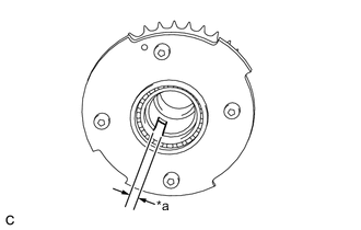
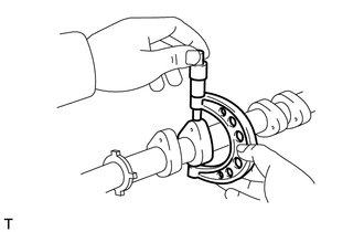
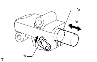
*a Keyway Using a vernier caliper, measure the keyway of the camshaft timing gear assembly eccentric shaft cutout.
Standard Width 5.9 to 6.2 mm (0.232 to 0.244 in.) Maximum Width 6.7 mm (0.264 in.) If the width is greater than the maximum, replace the camshaft timing gear assembly.
-
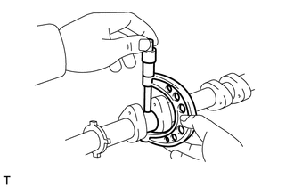
Rotate the keyway of the camshaft timing gear assembly eccentric shaft by hand.
Standard Rotates smoothly If the result is not as specified, replace the camshaft timing gear assembly.
-
-
INSPECT CAMSHAFT TIMING EXHAUST GEAR ASSEMBLY
-
Check the lock of the camshaft timing exhaust gear assembly.
-
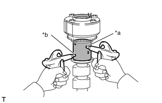
Secure the camshaft in a vise between aluminum plates, and confirm that the camshaft timing exhaust gear assembly is locked.
Note
Do not overtighten the vise.
-
-
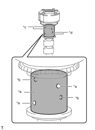
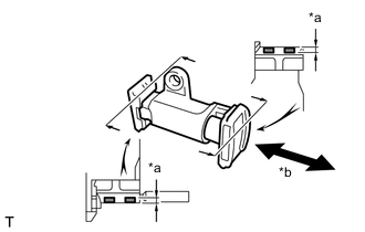
*a Open *b Close *c Advanced Side Path *d Retard Side Path *e Vinyl Tape Release the lock pin.
-
Cover the 4 oil paths of the cam journal with vinyl tape as shown in the illustration.
-
Make a hole in the tape on the advance side path and retard side path as shown in the illustration.
-
*a Advance Side Path *b Retard Side Path Apply approximately 200 kPa (2.0 kgf/cm2, 29 psi) of air pressure to the 2 open paths (the advance side path and the retard side path).
Note
The lock pin is released and the camshaft timing exhaust gear assembly turns in the advance direction.
-
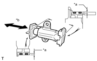
*a Advance Side Path *b Retard Side Path *c Hold Pressure *d Decompress Check that the camshaft timing exhaust gear assembly rotates in the retard direction when reducing the air pressure applied to the advance side path.
Tech Tips
This operation releases the lock pin for the most retarded position.
-
When the camshaft timing exhaust gear assembly reaches the most advanced position, release the air pressure from the retard side path, and then release the air pressure from the advance side path.
Note
Do not release the air pressure from the retard side path first. The camshaft timing exhaust gear may abruptly shift in the advance direction and break the lock pin.
-
-
Check for smooth rotation.
-
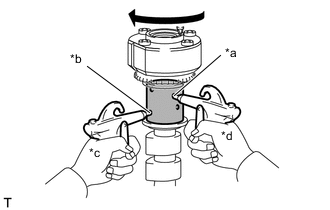
Turn the camshaft timing exhaust gear assembly within its movable range (18.5°) 2 or 3 times, but do not turn it to the most advanced position. Make sure that the gear turns smoothly.
Note
Do not use air pressure to perform the smooth operation check.
-
-
Check the lock at the most advanced position.
-
Confirm that the camshaft timing exhaust gear assembly locks at the most advanced position.
-
-
-
INSPECT CYLINDER HEAD SET BOLT
-
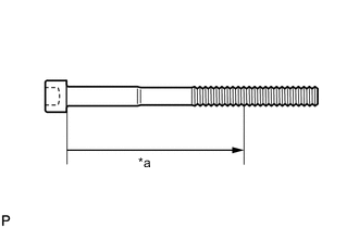
*a Measurement Point Using a vernier caliper, measure the diameter of the thread at the measurement point.
Standard Diameter 10.85 to 11.00 mm (0.427 to 0.433 in.) Minimum Diameter 10.6 mm (0.417 in.) Measurement Point for Intake Side Bolt 90 mm (3.54 in.) for Exhaust Side Bolt 85 mm (3.35 in.) Note
-
If the diameter is less than the minimum, replace the cylinder head set bolt. Failure to do so may lead to engine damage.
-
If there is any thread deformation, replace the cylinder head set bolt with a new one.
-
-
-
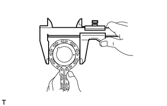
INSPECT CHAIN SUB-ASSEMBLY
-
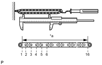
*a Measurement Area Using a spring scale, pull the chain sub-assembly with a force of 147 N (15 kgf, 33 lbf) and measure the length of the chain sub-assembly using a vernier caliper.
Maximum Chain Elongation 136.9 mm (5.39 in.) Tech Tips
Perform the measurement at 3 random places. If the elongation is more than the maximum, replace the chain sub-assembly.
-
-
INSPECT NO. 2 CHAIN SUB-ASSEMBLY
-
*a Measurement Area Using a spring scale, pull the No. 2 chain sub-assembly with a force of 147 N (15 kgf, 33 lbf) and measure the length of the No. 2 chain sub-assembly using a vernier caliper.
Maximum Chain Elongation 137.6 mm (5.42 in.) If the elongation is greater than the maximum, replace the No. 2 chain sub-assembly.
Tech Tips
Perform the measurement at 3 random places.
-
-
INSPECT CRANKSHAFT TIMING GEAR
-
Place the chain sub-assembly around the crankshaft timing gear.
-
Using a vernier caliper, measure the sprocket diameter with the chain sub-assembly.
Minimum Sprocket Diameter (with Chain Sub-assembly) 61.4 mm (2.42 in.) Tech Tips
The vernier caliper must contact the chain rollers when measuring.
If the diameter is less than the minimum, replace the chain sub-assembly and crankshaft timing gear.
-
-
INSPECT CRANKSHAFT TIMING SPROCKET LH
-
Place the chain sub-assembly around the crankshaft timing sprocket LH.
-

Using a vernier caliper, measure the sprocket diameter with the chain sub-assembly.
Minimum Sprocket Diameter (with Chain Sub-assembly) 61.4 mm (2.42 in.) Tech Tips
The vernier caliper must contact the crankshaft timing sprocket LH when measuring.
If the diameter is less than the minimum, replace the chain sub-assembly and crankshaft timing sprocket LH.
-
-
INSPECT NO. 1 CHAIN TENSIONER ASSEMBLY
-
*a Plunger *b Stopper Plate *c Moves Smoothly Turn the stopper plate clockwise to release the lock. Push the plunger and check that it moves smoothly.
If the plunger does not move smoothly, replace the No. 1 chain tensioner assembly.
-
-
INSPECT NO. 2 CHAIN TENSIONER ASSEMBLY
*a Depth *b Moves Smoothly
-
Check that the plunger moves smoothly.
-
Measure the depth of wear of the No. 2 chain tensioner assembly.
Maximum Depth 0.9 mm (0.0354 in.) If the depth is more than the maximum, replace the No. 2 chain tensioner assembly.
-
-
INSPECT NO. 3 CHAIN TENSIONER ASSEMBLY
*a Depth *b Moves Smoothly
-
Check that the plunger moves smoothly.
-
Measure the depth of wear of the No. 3 chain tensioner assembly.
Maximum Depth 0.9 mm (0.0354 in.) If the depth is more than the maximum, replace the No. 3 chain tensioner assembly.
-
-
INSPECT CHAIN TENSIONER SLIPPER
-
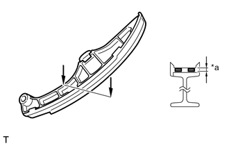
*a Depth for Bank 1:
-
Measure the depth of wear of the chain tensioner slipper.
Maximum Depth 1.0 mm (0.0394 in.) If the depth is more than the maximum, replace the chain tensioner slipper.
-
-
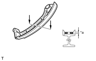
*a Depth for Bank 2:
-
Measure the depth of wear of the chain tensioner slipper.
Maximum Depth 1.0 mm (0.0394 in.) If the depth is more than the maximum, replace the chain tensioner slipper.
-
-
-
INSPECT NO. 1 CHAIN VIBRATION DAMPER
-
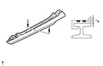
*a Depth for Bank 1:
-
Measure the depth of wear of the No. 1 chain vibration damper.
Maximum Depth 1.0 mm (0.0394 in.) If the depth is more than the maximum, replace the No. 1 chain vibration damper.
-
-
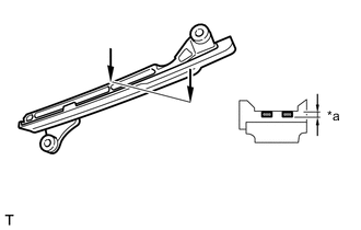
*a Depth for Bank 2:
-
Measure the depth of wear of the No. 1 chain vibration damper.
Maximum Depth 1.0 mm (0.0394 in.) If the depth is more than the maximum, replace the No. 1 chain vibration damper.
-
-
-
INSPECT CYLINDER HEAD SUB-ASSEMBLY