CAMSHAFT REMOVAL
CAUTION / NOTICE / HINT
The necessary procedures (adjustment, calibration, initialization, or registration) that must be performed after parts are removed, installed, or replaced during the camshaft removal/installation are shown below.
| Replacement Part or Procedure | Necessary Procedure | Effect/Inoperative when not Performed | Link |
|---|---|---|---|
| Disconnect cable from negative battery terminal | Memorize steering angle neutral point | Parking assist monitor system | |
| Lane departure alert system (w/ Steering Control) | |||
| Pre-crash safety system | |||
| Adaptive high beam system | |||
| Reset power trunk lid | Power trunk lid system | ||
|
Inspection After Repair |
|
|
PROCEDURE
-
REMOVE TIMING CHAIN COVER ASSEMBLY
-
SET NO. 1 CYLINDER TO TDC / COMPRESSION
-
REMOVE NO. 1 CHAIN TENSIONER ASSEMBLY (for Bank 1)
-
REMOVE CHAIN TENSIONER SLIPPER (for Bank 1)
-
REMOVE NO. 1 CHAIN VIBRATION DAMPER (for Bank 1)
-
REMOVE CHAIN SUB-ASSEMBLY (for Bank 1)
-
REMOVE NO. 3 CHAIN TENSIONER ASSEMBLY
-
REMOVE NO. 1 CHAIN TENSIONER ASSEMBLY (for Bank 2)
-
REMOVE CHAIN TENSIONER SLIPPER (for Bank 2)
-
REMOVE NO. 1 CHAIN VIBRATION DAMPER (for Bank 2)
-
REMOVE CHAIN SUB-ASSEMBLY (for Bank 2)
-
REMOVE NO. 2 CHAIN TENSIONER ASSEMBLY
-
REMOVE OIL REFLECTOR PLATE LH
-
REMOVE CAMSHAFT BEARING CAP (for Bank 1)
Tech Tips
When rotating the camshafts without the chain sub-assemblies installed, make sure that the valves do not contact the pistons. If contact occurs between the valves and pistons, damage may result.
-
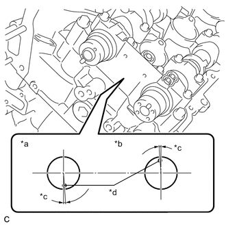
*a Intake Side *b Exhaust Side *c 4° *d Knock Pin Make sure that the knock pin of each camshaft is positioned as shown in the illustration.
-
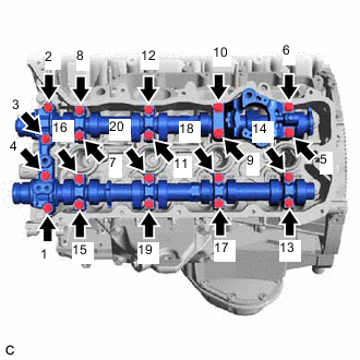
Uniformly loosen and remove the 20 bolts in the order shown in the illustration.
Tech Tips
Uniformly loosen the bolts while keeping the camshaft level.
-
Remove the 8 camshaft bearing caps.
Tech Tips
Arrange the removed parts in such a way that they can be installed to their original locations.
-
-
REMOVE NO. 3 CAMSHAFT SUB-ASSEMBLY
-
Remove the No. 3 camshaft sub-assembly from the cylinder head LH.
-
-
REMOVE NO. 4 CAMSHAFT SUB-ASSEMBLY
-
Remove the No. 4 camshaft sub-assembly from the cylinder head LH.
-
-
REMOVE OIL REFLECTOR PLATE RH
-
REMOVE CAMSHAFT BEARING CAP (for Bank 2)
Tech Tips
When rotating the camshafts without the chain assemblies installed, be careful to ensure that the valves do not contact the pistons. If contact occurs between the valves and pistons, damage may result.
-
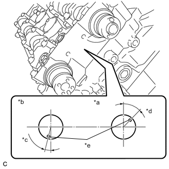
*a Intake Side *b Exhaust Side *c 14° *d 44° *e Knock Pin Make sure that the knock pin of each camshaft is positioned as shown in the illustration.
-
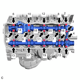
Uniformly loosen and remove the 20 bolts in the order shown in the illustration.
Tech Tips
Uniformly loosen the bolts while keeping the camshaft level.
-
Remove the 8 camshaft bearing caps.
Tech Tips
Arrange the removed parts in such a way that they can be installed to their original locations.
-
-
REMOVE CAMSHAFT
-
Remove the camshaft from the cylinder head sub-assembly.
-
-
REMOVE NO. 2 CAMSHAFT
-
Remove the No. 2 camshaft from the cylinder head sub-assembly.
-