FUEL SYSTEM SYSTEM DIAGRAM

-
FUEL FLOW DIAGRAM
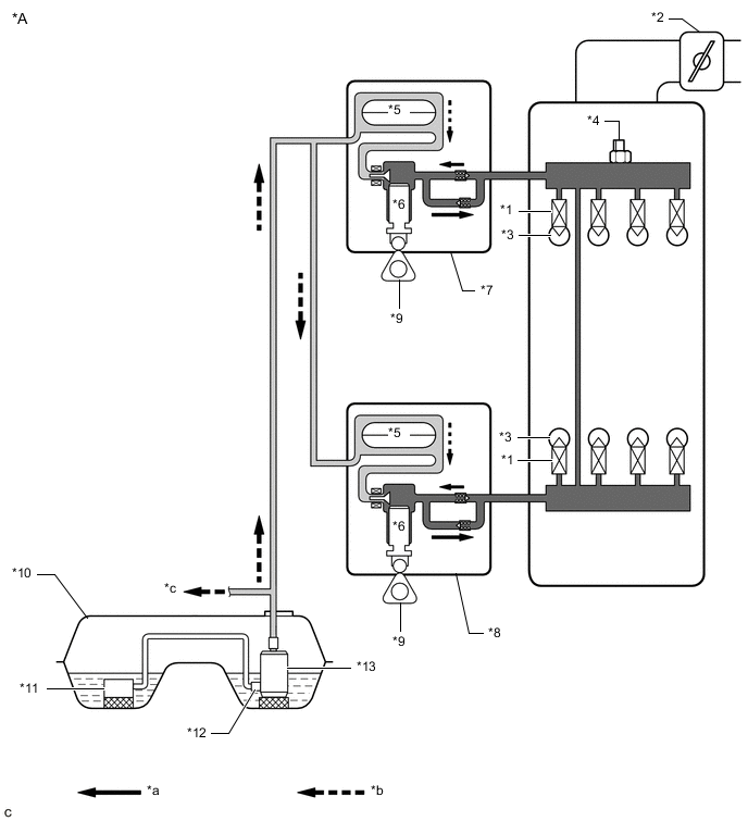
*A for Direct Injection - - *1 Direct Fuel Injector Assembly *2 Throttle Body Assembly *3 Cylinder *4 Fuel Pressure Sensor *5 Fuel Pressure Pulsation Damper Assembly *6 Plunger *7 Fuel Pump with Seal Sub-assembly (for Bank 1) *8 Fuel Pump with Seal Sub-assembly (for Bank 2) *9 Camshaft *10 Fuel Tank Assembly *11 Fuel Tank Vent Tube Assembly
- No. 2 Fuel Sender Gauge Assembly
*12 Jet Pump *13 Fuel Suction Tube with Pump and Gauge Assembly
- Fuel Pressure Regulator Assembly
- Fuel Sender Gauge Assembly
- Fuel Pump with Filter Assembly
- Fuel Filter
- - *a High Pressure Fuel Line *b Low Pressure Fuel Line *c To Port Fuel Injector Assembly - - 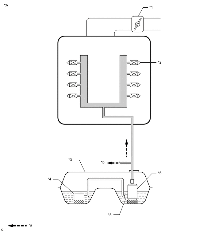
*A for Port Injection - - *1 Throttle Body Assembly *2 Port Fuel Injector Assembly *3 Fuel Tank Assembly *4 Fuel Tank Vent Tube Assembly
- No. 2 Fuel Sender Gauge Assembly
*5 Jet Pump *6 Fuel Suction Tube with Pump and Gauge Assembly
- Fuel Pressure Regulator Assembly
- Fuel Sender Gauge Assembly
- Fuel Pump with Filter Assembly
- Fuel Filter
*a Low Pressure Fuel Line *b To Fuel Pump with Seal Sub-assembly -
ELECTRICAL CONTROL DIAGRAM
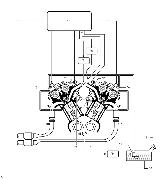
*1 Direct Fuel Injector Assembly *2 Port Fuel Injector Assembly *3 Fuel Pressure Sensor *4 Fuel Pump with Seal Sub-assembly (for Bank 1) *5 Fuel Pump with Seal Sub-assembly (for Bank 2) *6 Injector Driver *7 ECM *8 Fuel Tank Assembly *9 Fuel Pump Control ECU Assembly *10 Fuel Suction Tube with Pump and Gauge Assembly
- Fuel Pressure Regulator Assembly
- Fuel Sender Gauge Assembly
- Fuel Pump with Filter Assembly
- Fuel Filter
*11 Fuel Tank Cap Assembly - - -
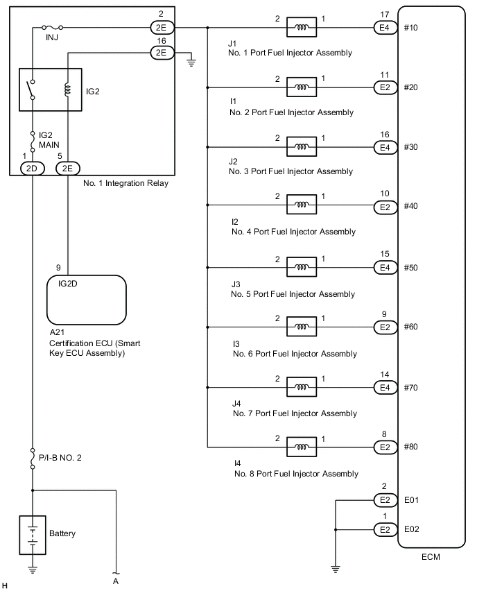
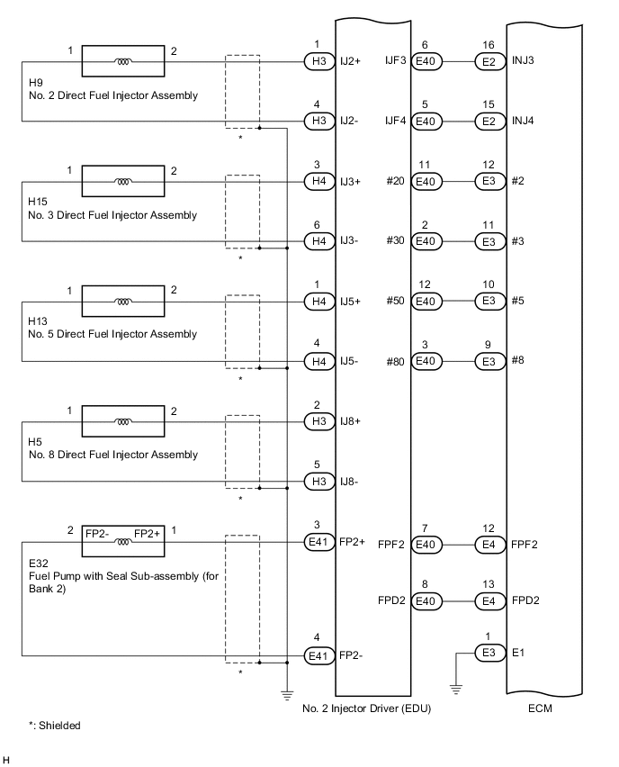
HIGH PRESSURE SIDE FUEL SYSTEM WIRING DIAGRAM
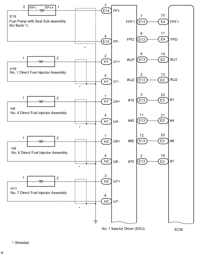
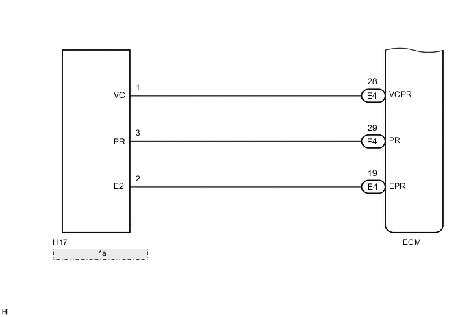
*a Fuel Delivery Pipe LH (Fuel Pressure Sensor) -
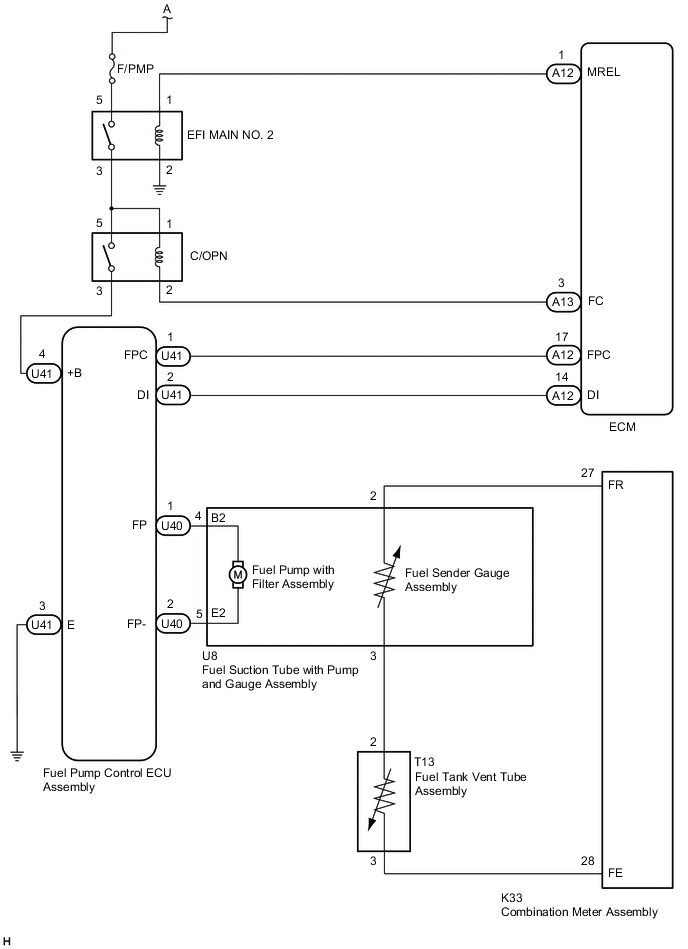
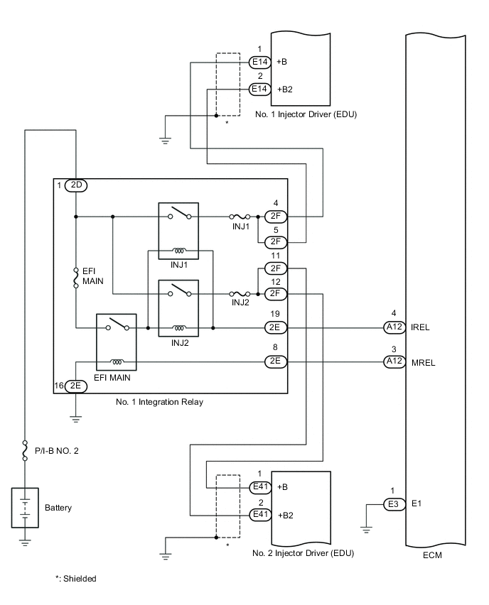
LOW PRESSURE SIDE FUEL SYSTEM WIRING DIAGRAM