CYLINDER BLOCK INSPECTION
PROCEDURE
-
INSPECT CYLINDER BLOCK FOR WARPAGE
-
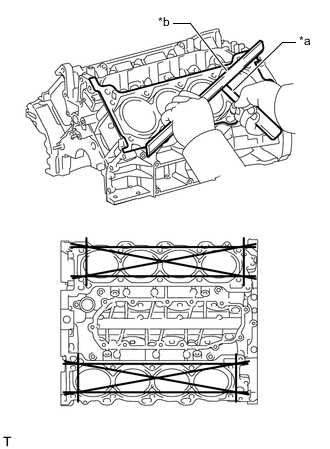
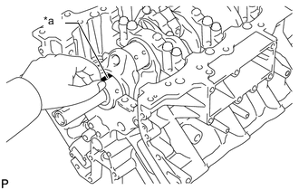
*a Feeler Gauge *b Precision Straightedge Using a precision straightedge and feeler gauge, check the surfaces that contact the cylinder head gaskets for warpage.
Maximum Warpage 0.05 mm (0.00197 in.) If the warpage is greater than the maximum, replace the cylinder block sub-assembly.
-
Visually check the cylinder for vertical scratches.
If deep scratches are present, rebore all 8 cylinders.
If necessary, replace the cylinder block sub-assembly.
-
-
INSPECT CYLINDER BORE
-
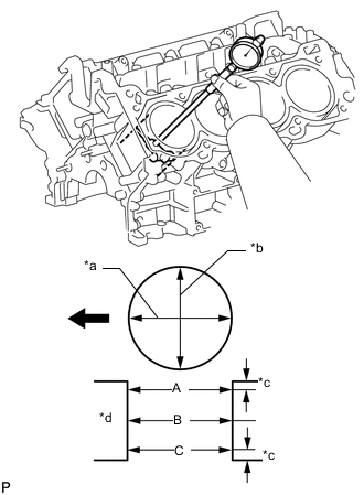
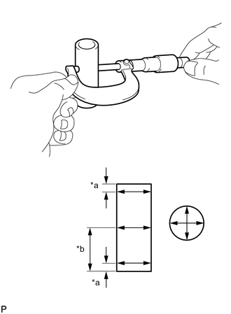
*a Axial Direction *b Thrust Direction *c 10 mm (0.394 in.) *d Center Using a cylinder gauge, measure the cylinder bore diameter at the positions (A), (B) and (C) in the thrust and axial directions.
Reference Value (New Parts) 94.000 to 94.012 mm (3.70078 to 3.70125 in.) Maximum Diameter 94.200 mm (3.70865 in.) If the diameter is greater than the maximum, replace the cylinder block sub-assembly.
-
-
INSPECT PISTON
-
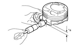
*a Distance Using a micrometer, measure the piston diameter at the position shown in the illustration.
Distance 14.5 mm (0.571 in.) Reference Value (New Parts) 93.961 to 93.991 mm (3.69924 to 3.70043 in.) Minimum Diameter 93.830 mm (3.69409 in.) If the diameter is less than the minimum, replace the piston with pin sub-assembly.
-
-
INSPECT PISTON OIL CLEARANCE
-
Measure the cylinder bore diameter in the thrust direction.
-
Subtract the piston diameter measurement from the cylinder bore diameter measurement.
Reference Value (New Parts) 0.010 to 0.032 mm (0.000394 to 0.00126 in.) Maximum Oil Clearance 0.370 mm (0.0146 in.) If the oil clearance is greater than the maximum, replace all the piston with pin sub-assembly. If necessary, replace the cylinder block sub-assembly.
-
-
INSPECT RING GROOVE CLEARANCE
-
*a Feeler Gauge Using a feeler gauge, measure the clearance between a new piston ring and the wall of the ring groove.
Standard Ring Groove Clearance Item Specified Condition No. 1 Compression Ring 0.020 to 0.070 mm (0.000787 to 0.00276 in.) No. 2 Compression Ring 0.020 to 0.060 mm (0.000787 to 0.00236 in.) Oil Ring 0.020 to 0.070 mm (0.000787 to 0.00276 in.) If the clearance is not as specified, replace the piston with pin sub-assembly.
-
-
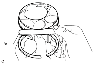
INSPECT PISTON RING END GAP
-
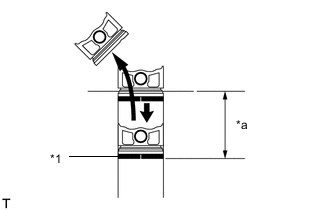
*1 Piston Ring *a Approximately 60 mm (2.36 in.) Insert the piston ring into the cylinder bore.
-
Using a piston, push the piston ring a little beyond the bottom of the ring travel, 60 mm (2.36 in.) from the top of the cylinder block sub-assembly.
-
*a Feeler Gauge Using a feeler gauge, measure the piston ring end gap.
Standard End Gap Item Specified Condition No. 1 Compression Ring 0.23 to 0.28 mm (0.00906 to 0.0110 in.) No. 2 Compression Ring 0.35 to 0.45 mm (0.0138 to 0.0177 in.) Oil Ring 0.1 to 0.2 mm (0.00394 to 0.00787 in.) Maximum End Gap Item Specified Condition No. 1 Compression Ring 0.40 mm (0.0157 in.) No. 2 Compression Ring 0.50 mm (0.0197 in.) Oil Ring 0.45 mm (0.0177 in.) If the end gap is more than the maximum, replace the piston ring. If the end gap is more than the maximum even with a new piston ring, replace the cylinder block sub-assembly.
-
-
INSPECT PISTON PIN OIL CLEARANCE
-
Check each mark on the piston, piston pin and connecting rod.
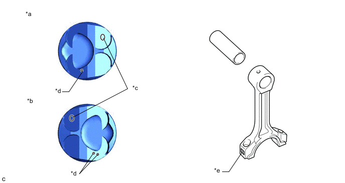
*a for Bank 1 *b for Bank 2 *c Piston Pin Hole Inside Diameter Mark *d Front Mark *e Connecting Rod Bush Inside Diameter Mark - - -
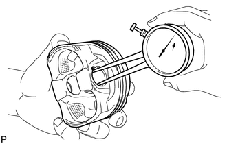
Using a caliper gauge, measure the inside diameter of the piston pin hole.
Standard Piston Pin Hole Inside Diameter Mark Specified Condition A 21.998 to 22.001 mm (0.86606 to 0.86618 in.) B 22.002 to 22.004 mm (0.86622 to 0.86630 in.) C 22.005 to 22.007 mm (0.86634 to 0.86642 in.) If the diameter is greater than the maximum, replace the piston with pin sub-assembly.
-
*a 5 mm (0.197 in.) *b 28 mm (1.10 in.) Using a micrometer, measure the piston pin diameter.
Standard Piston Pin Diameter Mark Specified Condition A 21.997 to 22.000 mm (0.86602 to 0.86614 in.) B 22.001 to 22.003 mm (0.86618 to 0.86626 in.) C 22.004 to 22.006 mm (0.86630 to 0.86638 in.) If the diameter is less than the minimum, replace the piston with pin sub-assembly.
-
Subtract the piston pin diameter measurement from the piston pin hole inside diameter measurement.
Standard Oil Clearance -0.002 to 0.004 mm (-0.00008 to 0.00016 in.) Maximum Oil Clearance 0.015 mm (0.000591 in.) If the oil clearance is more than the maximum, replace the piston with pin sub-assembly.
-
*a Caliper Gauge Using a caliper gauge, measure the inside diameter of the connecting rod bush.
Standard Bush Inside Diameter Mark Specified Condition A 22.005 to 22.008 mm (0.86634 to 0.86645 in.) B 22.009 to 22.011 mm (0.86649 to 0.86657 in.) C 22.012 to 22.014 mm (0.86661 to 0.86669 in.) If the diameter is greater than the maximum, replace the piston connecting rod sub-assembly.
-
Subtract the piston pin diameter measurement from the bushing inside diameter measurement.
Standard Oil Clearance 0.005 to 0.011 mm (0.000197 to 0.000433 in.) Maximum Oil Clearance 0.030 mm (0.00118 in.) If the oil clearance is greater than the maximum, replace the piston with pin sub-assembly or connecting rod sub-assembly.
-
-
INSPECT CONNECTING ROD SUB-ASSEMBLY
-
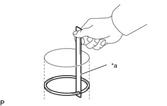
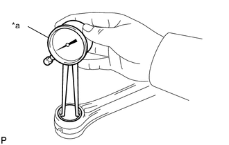
Using a connecting rod aligner and feeler gauge, check the connecting rod alignment.
-
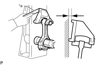
*a Feeler Gauge Check for misalignment.
Maximum Misalignment 0.05 mm (0.00197 in.) per 100 mm (3.94 in.) If the misalignment is greater than the maximum, replace the connecting rod sub-assembly.
-
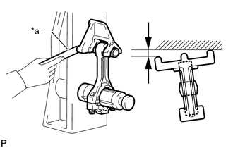
*a Feeler Gauge Check for twist.
Maximum Twist 0.15 mm (0.00591 in.) per 100 mm (3.94 in.) If the twist is greater than the maximum, replace the connecting rod sub-assembly.
-
-
-
INSPECT CONNECTING ROD BOLT
-
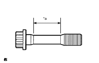
*a Measurement Area Using a vernier caliper, measure the diameter of the connecting rod bolt at several points within the area shown in the illustration.
Standard Diameter 8.5 to 8.6 mm (0.335 to 0.339 in.) Minimum Diameter 8.3 mm (0.327 in.) If the diameter is less than the minimum, replace the connecting rod bolt.
Tech Tips
-
If the diameter is less than the minimum, replace the connecting rod bolt with a new one. Failure to do so may lead to engine damage.
-
If there is any thread deformation, replace the connecting rod bolt with a new one.
-
-
-
INSPECT CRANKSHAFT
-
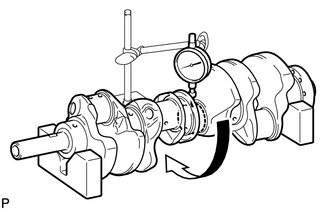
Inspect for runout.
-
Place the crankshaft on V-blocks.
-
Using a dial indicator, measure the runout at the center journal.
Maximum Runout 0.01 mm (0.000394 in.) If the runout is more than the maximum, replace the crankshaft.
-
-
Inspect the main journals.
-
Using a micrometer, measure the diameter of each main journal.
Standard Journal Diameter 67.000 to 69.988 mm (2.64 to 2.76 in.) If the diameter is not as specified, check the oil clearance. If necessary, replace the crankshaft.
-
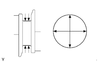
Check each main journal for taper and out-of-round as shown in the illustration.
Maximum Taper and Out-of-round 0.02 mm (0.000787 in.) If the taper or out-of-round is more than the maximum, replace the crankshaft.
-
-
Inspect the crank pins.
-
Using a micrometer, measure the diameter of each crank pin.
Standard Crank Pin Diameter 47.982 to 48.000 mm (1.88905 to 1.88976 in.) If the diameter is not as specified, check the oil clearance. If necessary, replace the crankshaft.
-
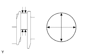
Check each crank pin for taper and out-of-round as shown in the illustration.
Maximum Taper and Out-of-round 0.02 mm (0.000787 in.) If the taper or out-of-round is more than the maximum, replace the crankshaft.
-
-
-
INSPECT CRANKSHAFT OIL CLEARANCE
-
Check the crank journal and crankshaft bearing for pitting and scratches.
Tech Tips
If the journal or crankshaft bearing is damaged, replace the crankshaft bearing.
-
Install the crankshaft bearing.
-
Place the crankshaft on the cylinder block sub-assembly.
-
*a Plastigage Lay a strip of Plastigage across each journal.
-
Confirm the front marks and numbers, and install the crankshaft bearing caps to the cylinder block sub-assembly.
Note
-
Do not apply engine oil to the crankshaft bearings or crankshaft journals.
-
Do not turn the crankshaft.
Tech Tips
A number is marked on each crankshaft bearing cap to indicate the installation position.
-
-
Remove the crankshaft bearing caps.
-
Measure the Plastigage at its widest point.
Standard Oil Clearance Item Specified Condition No. 1, No. 5 Journal 0.017 to 0.030 mm (0.000669 to 0.00118 in.) No. 2, No. 3 and No. 5 Journal 0.024 to 0.037 mm (0.000945 to 0.00146 in.) Maximum Oil Clearance Item Specified Condition No. 1, No. 5 Journal 0.050 mm (0.00197 in.) No. 2, No. 3 and No. 5 Journal 0.060 mm (0.00236 in.) If the oil clearance is greater than the maximum, replace the crankshaft bearings. If necessary, replace the crankshaft.
-
If replacing a bearing, replace it with one having the same number. If the number of the bearing cannot be determined, select the correct bearing by adding together the numbers imprinted on the cylinder block sub-assembly and crankshaft. Refer to the table below for the appropriate bearing number. There are 6 sizes of standard bearings. For No. 1 and No. 5 journals, use bearings marked 4, 5, 6, 7, 8 or 9. For other journals, use bearings marked 3, 4, 5, 6, 7 or 8.
Tech Tips
EXAMPLE: Cylinder block sub-assembly "07" + Crankshaft "06" = Total number 13 (Use upper bearing "6" and lower bearing "7")
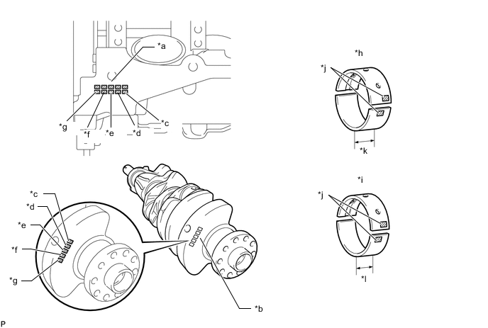
*a Cylinder Block Main Journal Diameter Number Mark *b Crankshaft Main Journal Diameter Number Mark *c No. 1 Journal Bearing *d No. 2 Journal Bearing *e No. 3 Journal Bearing *f No. 4 Journal Bearing *g No. 5 Journal Bearing *h No. 1 and No. 5 Journal Bearing *i No. 2, No. 3 and No. 5 Journal Bearing *j Bearing Number *k 22.5 mm (0.886 in.) *l 21 mm (0.827 in.) Standard Crankshaft Main Journal Diameter Item Specified Condition Mark 00 66.999 to 67.000 mm (2.63775 to 2.63779 in.) Mark 01 66.998 to 66.999 mm (2.63771 to 2.63775 in.) Mark 02 66.997 to 66.998 mm (2.63767 to 2.63771 in.) Mark 03 66.996 to 66.997 mm (2.63763 to 2.63767 in.) Mark 04 66.995 to 66.996 mm (2.63759 to 2.63763 in.) Mark 05 66.994 to 66.995 mm (2.63755 to 2.63759 in.) Mark 06 66.993 to 66.994 mm (2.63751 to 2.63755 in.) Mark 07 66.992 to 66.993 mm (2.63748 to 2.63751 in.) Mark 08 66.991 to 66.992 mm (2.63744 to 2.63748 in.) Mark 09 66.990 to 66.991 mm (2.63740 to 2.63744 in.) Mark 10 66.989 to 66.990 mm (2.63736 to 2.63740 in.) Mark 11 66.988 to 66.989 mm (2.63732 to 2.63736 in.) Standard Bearing Center Wall Thickness for No. 1 and No. 5 Journals Cylinder Block Number Mark + Crankshaft Number Mark Upper Bearing Number Mark Specified Condition 00 to 02 4 2.501 to 2.504 mm (0.0985 to 0.0986 in.) 03 to 05 5 2.504 to 2.507 mm (0.0986 to 0.0987 in.) 06 to 08 5 2.504 to 2.507 mm (0.0986 to 0.0987 in.) 09 to 11 6 2.507 to 2.510 mm (0.0987 to 0.0988 in.) 12 to 14 6 2.507 to 2.510 mm (0.0987 to 0.0988 in.) 15 to 17 7 2.510 to 2.513 mm (0.0988 to 0.0989 in.) 18 to 20 7 2.510 to 2.513 mm (0.0988 to 0.0989 in.) 21 to 23 8 2.513 to 2.516 mm (0.0989 to 0.0991 in.) 24 to 26 8 2.513 to 2.516 mm (0.0989 to 0.0991 in.) 27 to 28 9 2.516 to 2.519 mm (0.0991 to 0.0992 in.) Standard Bearing Center Wall Thickness for No. 1 and No. 5 Journals Cylinder Block Number Mark + Crankshaft Number Mark Lower Bearing Number Mark Specified Condition 00 to 02 5 2.488 to 2.491 mm (0.0980 to 0.0981 in.) 03 to 05 5 2.488 to 2.491 mm (0.0980 to 0.0981 in.) 06 to 08 6 2.491 to 2.494 mm (0.0981 to 0.0982 in.) 09 to 11 6 2.491 to 2.494 mm (0.0981 to 0.0982 in.) 12 to 14 7 2.494 to 2.497 mm (0.0982 to 0.0983 in.) 15 to 17 7 2.494 to 2.497 mm (0.0982 to 0.0983 in.) 18 to 20 8 2.497 to 2.500 mm (0.0983 to 0.0984 in.) 21 to 23 8 2.497 to 2.500 mm (0.0983 to 0.0984 in.) 24 to 26 9 2.500 to 2.503 mm (0.0984 to 0.0985 in.) 27 to 28 9 2.500 to 2.503 mm (0.0984 to 0.0985 in.) Standard Bearing Center Wall Thickness for No. 2, No. 3 and No. 4 Journals Cylinder Block Number Mark + Crankshaft Number Mark Upper Bearing Number Mark Specified Condition 00 to 02 3 2.482 to 2.485 mm (0.0977 to 0.0978 in.) 03 to 05 4 2.485 to 2.488 mm (0.0978 to 0.0980 in.) 06 to 08 4 2.485 to 2.488 mm (0.0978 to 0.0980 in.) 09 to 11 5 2.488 to 2.491 mm (0.0980 to 0.0981 in.) 12 to 14 5 2.488 to 2.491 mm (0.0980 to 0.0981 in.) 15 to 17 6 2.491 to 2.494 mm (0.0981 to 0.0982 in.) 18 to 20 6 2.491 to 2.494 mm (0.0981 to 0.0982 in.) 21 to 23 7 2.494 to 2.497 mm (0.0982 to 0.0983 in.) 24 to 26 7 2.494 to 2.497 mm (0.0982 to 0.0983 in.) 27 to 28 8 2.497 to 2.500 mm (0.0983 to 0.0984 in.) Standard Bearing Center Wall Thickness for Other Journals Cylinder Block Number Mark + Crankshaft Number Mark Lower Bearing Number Mark Specified Condition 00 to 02 4 2.501 to 2.504 mm (0.0985 to 0.0986 in.) 03 to 05 4 2.501 to 2.504 mm (0.0985 to 0.0986 in.) 06 to 08 5 2.504 to 2.507 mm (0.0986 to 0.0987 in.) 09 to 11 5 2.504 to 2.507 mm (0.0986 to 0.0987 in.) 12 to 14 6 2.507 to 2.510 mm (0.0987 to 0.0988 in.) 15 to 17 6 2.507 to 2.510 mm (0.0987 to 0.0988 in.) 18 to 20 7 2.510 to 2.513 mm (0.0988 to 0.0989 in.) 21 to 23 7 2.510 to 2.513 mm (0.0988 to 0.0989 in.) 24 to 26 8 2.513 to 2.516 mm (0.0989 to 0.0991 in.) 27 to 28 8 2.513 to 2.516 mm (0.0989 to 0.0991 in.) -
Completely remove the Plastigage.
-
-
INSPECT CRANKSHAFT BEARING CAP SET BOLT
-
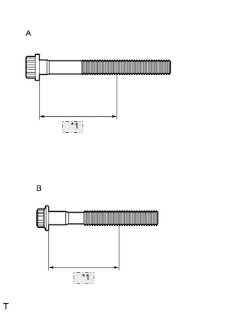
*1 47 mm Using a vernier caliper, measure the diameter of the threads at the measurement point.
Standard Diameter Bolt A 10.8 to 11.0 mm (0.425 to 0.433 in.) Bolt B 9.8 to 10.0 mm (0.386 to 0.394 in.) Minimum Diameter Bolt A 10.7 mm (0.421 in.) Bolt B 9.7 mm (0.382 in.) Measurement Point (Distance from the Seat) 47 mm (1.85 in.) Tech Tips
-
If the diameter is less than the minimum, replace the crankshaft bearing cap set bolt. Failure to do so may lead to engine damage.
-
If there is any thread deformation, replace the crankshaft bearing cap set bolt with a new one.
If the diameter is less than the minimum, replace the crankshaft bearing cap set bolt.
-
-
-
INSPECT NO. 1 OIL NOZZLE SUB-ASSEMBLY
-
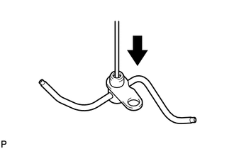
Push the check valve with a pin to check that it is not stuck.
If the check valve is stuck, replace the No. 1 oil nozzle sub-assembly.
-
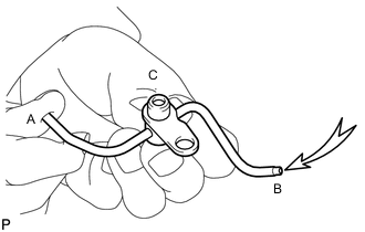
While covering (A), blow air into (B). Check that air does not leak through (C).
If air leaks, clean or replace the No. 1 oil nozzle sub-assembly.
Tech Tips
Perform the check again while covering (B) and blowing air into (A).
-
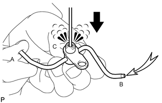
Push the check valve while covering (A), and blow air into (B). Check that air passes through (C).
Tech Tips
Perform the check again while covering (B) and blowing air into (A).
If air does not pass through, clean or replace the No. 1 oil nozzle sub-assembly.
-