KNOCK SENSOR INSTALLATION
PROCEDURE
-
INSTALL KNOCK SENSOR
Tech Tips
Perform "Inspection After Repair" after replacing a knock sensor.
-
w/ Canister Pump Module:
-
w/o Canister Pump Module:
-
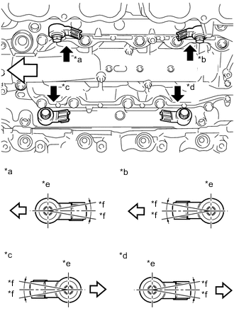
*a for Bank 2 Sensor 1 *b for Bank 2 Sensor 2 *c for Bank 1 Sensor 1 *d for Bank 1 Sensor 2 *e Up *f 10° 
Engine Front Install the 4 knock sensors to the cylinder block sub-assembly with the 4 bolts so that the knock sensors installation position is as shown in the illustration.
- Torque:
- 20 N*m { 204 kgf*cm, 15 ft.*lbf }
Note
-
Make sure that each knock sensor is in the correct position.
-
If a knock sensor has been struck or dropped, replace it.
-
Connect the 4 knock sensor connectors.
-
-
INSTALL CASE SEPARATOR
-
Install the case separator with the 4 bolts.
- Torque:
- 10 N*m { 102 kgf*cm, 7 ft.*lbf }
-
Connect the fuel pressure sensor connector.
-
-
INSTALL NO. 4 FUEL PIPE SUB-ASSEMBLY
-
INSTALL NO. 2 ENGINE COVER SUB-ASSEMBLY LH
-
INSTALL NO. 1 ENGINE COVER SUB-ASSEMBLY
-
INSTALL INTAKE AIR SURGE TANK ASSEMBLY
-
PERFORM INITIALIZATION
-
Perform "Inspection After Repair" after replacing a knock sensor.
-
w/ Canister Pump Module:
-
w/o Canister Pump Module:
-
-