CAMSHAFT POSITION SENSOR REMOVAL
CAUTION / NOTICE / HINT
The necessary procedures (adjustment, calibration, initialization, or registration) that must be performed after parts are removed, installed, or replaced during the battery removal/installation are shown below.
| Replacement Part or Procedure | Necessary Procedure | Effect/Inoperative when not Performed | Link |
|---|---|---|---|
| Disconnect cable from negative battery terminal | Memorize steering angle neutral point | Parking assist monitor system | |
| Lane departure alert system (w/ Steering Control) | |||
| Pre-crash safety system | |||
| Adaptive high beam system | |||
| Reset power trunk lid | Power trunk lid system |
PROCEDURE
-
PRECAUTION
Note
After turning the engine switch off, waiting time may be required before disconnecting the cable from the negative (-) battery terminal. Therefore, make sure to read the disconnecting the cable from the negative (-) battery terminal notices before proceeding with work.
-
DISCONNECT CABLE FROM NEGATIVE BATTERY TERMINAL (for LHD)
Note
When disconnecting the cable, some systems need to be initialized after the cable is reconnected.
-
REMOVE V-BANK COVER SUB-ASSEMBLY
-
REMOVE CAMSHAFT POSITION SENSOR
-
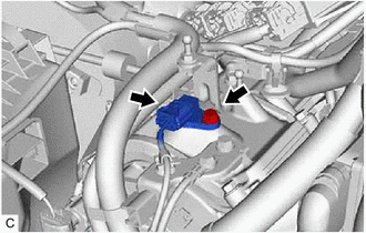
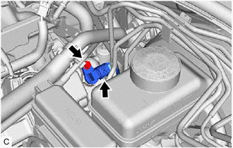
Disconnect the camshaft position sensor connector.
-
Remove the bolt and camshaft position sensor from the cylinder head cover sub-assembly.
Note
If the camshaft position sensor has been struck or dropped, replace it.
-
-
REMOVE VVT SENSOR (for Exhaust Side of Bank 1)
-
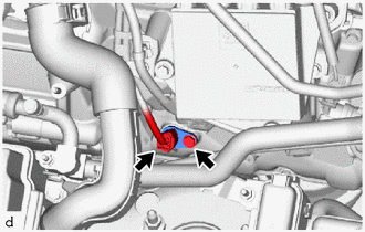
Disconnect the VVT sensor connector.
-
Remove the bolt and VVT sensor from the cylinder head cover sub-assembly LH.
Note
If the VVT sensor has been struck or dropped, replace it.
-
-
REMOVE VVT SENSOR (for Exhaust Side of Bank 2)
-
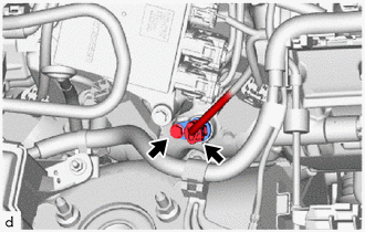
Disconnect the VVT sensor connector.
-
Remove the bolt and VVT sensor from the cylinder head cover sub-assembly.
Note
If the VVT sensor has been struck or dropped, replace it.
-
-
REMOVE BATTERY (for LHD)
-
REMOVE VVT SENSOR (for Intake Side of Bank 2)
-
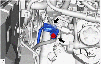
Disconnect the VVT sensor connector.
-
Remove the bolt and VVT sensor from the cylinder head cover sub-assembly.
Note
If the VVT sensor has been struck or dropped, replace it.
-
-
REMOVE NO. 3 FUEL PIPE SUB-ASSEMBLY
-
REMOVE VVT SENSOR (for Intake Side of Bank 1)
-
Disconnect the VVT sensor connector.
-
Remove the bolt and VVT sensor from the cylinder head cover sub-assembly LH.
Note
If the VVT sensor has been struck or dropped, replace it.
-