SFI SYSTEM(w/o Canister Pump Module), Diagnostic DTC:P1235, P1236
| DTC Code | DTC Name |
|---|---|
| P1235 | High Pressure Fuel Pump Circuit |
| P1236 | High Pressure Fuel Pump No. 2 Circuit |
DESCRIPTION
The fuel pump with seal sub-assembly (for high pressure side) is attached to the insulator, which is attached to the cylinder head cover. The pump activates according to the position of the cam on the intake side camshaft (bank 1 and bank 2). The fuel pump with seal sub-assembly (for high pressure side) increases the pressure of the fuel supplied from the fuel pump in the fuel tank to 2 to 18 MPa (20.4 to 183.5 kgf/cm2, 290 to 580 psi) according to the operating condition, and it feeds the fuel to the fuel delivery pipe.
| DTC No. | Detection Item | DTC Detection Condition | Trouble Area | MIL | Memory |
|---|---|---|---|---|---|
| P1235 | High Pressure Fuel Pump Circuit | Open or short in fuel pump with seal sub-assembly (for high pressure side of bank1) circuit for 1 second or more (1 trip detection logic). |
|
Comes on | DTC stored |
| P1236 | High Pressure Fuel Pump No. 2 Circuit | Open or short in fuel pump with seal sub-assembly (for high pressure side of bank2) circuit for 1 second or more (1 trip detection logic). |
|
Comes on | DTC stored |
MONITOR DESCRIPTION
The injector driver has the integrated circuit (IC) which monitors the electrical circuit between the spill control valve and injector driver. If an open circuit is detected, the IC sends the malfunction signal (FPD, FPD2) to the ECM. Then, the ECM will illuminate the MIL and store a DTC.
MONITOR STRATEGY
| Required Sensors/Components (Main) | Fuel pump with seal sub-assembly (for high pressure side) |
| Required Sensors/Components (Related) | Injector driver |
| Frequency of Operation | Continuous |
CONFIRMATION DRIVING PATTERN
-
Connect the GTS to the DLC3.
-
Turn the engine switch on (IG).
-
Turn the GTS on.
-
Clear the DTCs (even if no DTCs are stored, perform the clear DTC procedure).
-
Turn the engine switch off and wait for at least 30 seconds.
-
Turn the engine switch on (IG).
-
Turn the GTS on.
-
Start the engine.
-
Idle the engine for 10 seconds [A].
-
Enter the following menus: Powertrain / Engine / Trouble Codes [B].
-
Read the pending DTCs.
Tech Tips
-
If a pending DTC is output, the system is malfunctioning.
-
If a pending DTC is not output, perform the following procedure.
-
-
Enter the following menus: Powertrain / Engine / Utility / All Readiness.
-
Input the DTC: P1235 and P1236.
-
Check the DTC judgment result.
GTS Display Description NORMAL
-
DTC judgment completed
-
System normal
ABNORMAL
-
DTC judgment completed
-
System abnormal
INCOMPLETE
-
DTC judgment not completed
-
Perform driving pattern after confirming DTC enabling conditions
N/A
-
Unable to perform DTC judgment
-
Number of DTCs which do not fulfill DTC preconditions has reached ECU memory limit
Tech Tips
-
If the judgment result shows NORMAL, the system is normal.
-
If the judgment result shows ABNORMAL, the system has a malfunction.
-
If the judgment result shows INCOMPLETE or N/A, perform steps [A] and [B] again.
-
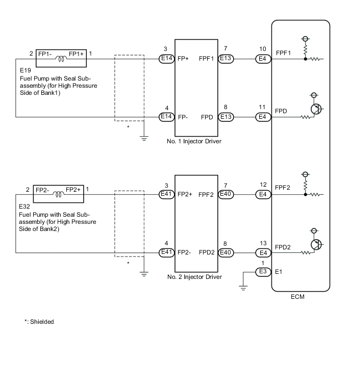
WIRING DIAGRAM
CAUTION / NOTICE / HINT
Tech Tips
-
Bank 1 refers to the bank that includes the No. 1 cylinder*.
*: The No. 1 cylinder is the cylinder which is farthest from the transmission.
-
Bank 2 refers to the bank that does not include the No. 1 cylinder.
-
If the current from the INJ1 relay is cut because DTC P062D is stored, DTC P1235 will be stored even if the fuel pump with seal sub-assembly (for high pressure side) is normal.
-
If the current from the INJ2 relay is cut because DTC P062E is stored, DTC P1236 will be stored even if the fuel pump with seal sub-assembly (for high pressure side) is normal.
-
Read freeze frame data using the GTS. The ECM records vehicle and driving condition information as freeze frame data the moment a DTC is stored. When troubleshooting, freeze frame data can help determine if the vehicle was moving or stationary, if the engine was warmed up or not, if the air fuel ratio was lean or rich, and other data from the time the malfunction occurred.
PROCEDURE
-
CHECK INJECTOR DRIVER (NO.1 AND NO.2)
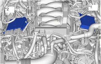
*1 No. 1 injector driver *2 No. 2 injector driver
-
Turn the engine switch off.
-
Interchange the No. 1 and No. 2 injector driver.
Note
Do not disconnect and reconnect the connectors with the engine switch on (IG), as the injector driver may be damaged.
-
Connect the GTS to the DLC3.
-
Turn the engine switch on (IG).
-
Turn the GTS on.
-
Clear the DTCs.
Note
Before clearing the DTCs, write them down.
Powertrain > Engine > Clear DTCs -
Start the engine.
-
Enter the following menus: Powertrain / Engine / Trouble Codes.
Powertrain > Engine > Trouble Codes -
Read the DTCs.
Result Result Proceed to DTCs do not change A DTCs change (change in malfunctioning cylinder or EDU code) B
B 
REPLACE INJECTOR DRIVER (NO.1 or NO. 2) Click here
A 
-
-
INSPECT FUEL PUMP WITH SEAL SUB-ASSEMBLY (FOR HIGH PRESSURE SIDE)
-
Inspect the fuel pump with seal sub-assembly (for high pressure side).
Tech Tips
Perform "Inspection After Repair" after replacing the fuel pump with seal sub-assembly (for high pressure side).
Result Proceed to OK NG
NG
REPLACE FUEL PUMP WITH SEAL SUB-ASSEMBLY (FOR HIGH PRESSURE SIDE) Click here
OK
-
-
CHECK HARNESS AND CONNECTOR (INJECTOR DRIVER - FUEL PUMP WITH SEAL SUB-ASSEMBLY (FOR HIGH PRESSURE SIDE))
-
Disconnect the E14 or E41 injector driver connector.
-
Disconnect the E19 or E32 fuel pump with seal sub-assembly (for high pressure side) connector.
-
Measure the resistance according to the value(s) in the table below.
Standard Resistance Tester Connection Condition Specified Condition E14-3 (FP+) - E19-1 (FP1+) Always Below 1 Ω E14-4 (FP-) - E19-2 (FP1-) Always Below 1 Ω E41-3 (FP2+) - E32-1 (FP2+) Always Below 1 Ω E41-4 (FP2-) - E32-2 (FP2-) Always Below 1 Ω E14-3 (FP+) or E19-1 (FP1+) - Body ground and other terminals Always 10 kΩ or higher E14-4 (FP-) or E19-2 (FP1-) - Body ground and other terminals Always 10 kΩ or higher E41-3 (FP2+) or E32-1 (FP2+) - Body ground and other terminals Always 10 kΩ or higher E41-4 (FP2-) or E32-2 (FP2-) - Body ground and other terminals Always 10 kΩ or higher Result Proceed to OK NG
NG
REPAIR OR REPLACE HARNESS OR CONNECTOR
OK
-
-
CHECK HARNESS AND CONNECTOR (ECM - INJECTOR DRIVER)
-
Disconnect the E4 ECM connector.
-
Disconnect the E13 or E40 injector driver connector.
-
Measure the resistance according to the value(s) in the table below.
Standard Resistance Tester Connection Condition Specified Condition E4-10 (FPF1) - E13-7 (FPF1) Always Below 1 Ω E4-11 (FPD) - E13-8 (FPD) Always Below 1 Ω E4-12 (FPF2) - E40-7 (FPF2) Always Below 1 Ω E4-13 (FPD2) - E40-8 (FPD2) Always Below 1 Ω E4-10 (FPF1) or E13-7 (FPF1) - Body ground and other terminals Always 10 kΩ or higher E4-11 (FPD) or E13-8 (FPD) - Body ground and other terminals Always 10 kΩ or higher E4-12 (FPF2) or E40-7 (FPF2) - Body ground and other terminals Always 10 kΩ or higher E4-13 (FPD2) or E40-8 (FPD2) - Body ground and other terminals Always 10 kΩ or higher Result Proceed to OK NG
OK
REPLACE ECM Click here
NG
REPAIR OR REPLACE HARNESS OR CONNECTOR
-