SFI SYSTEM(w/o Canister Pump Module), Diagnostic DTC:P0230
| DTC Code | DTC Name |
|---|---|
| P0230 | Fuel Pump Primary Circuit |
DESCRIPTION
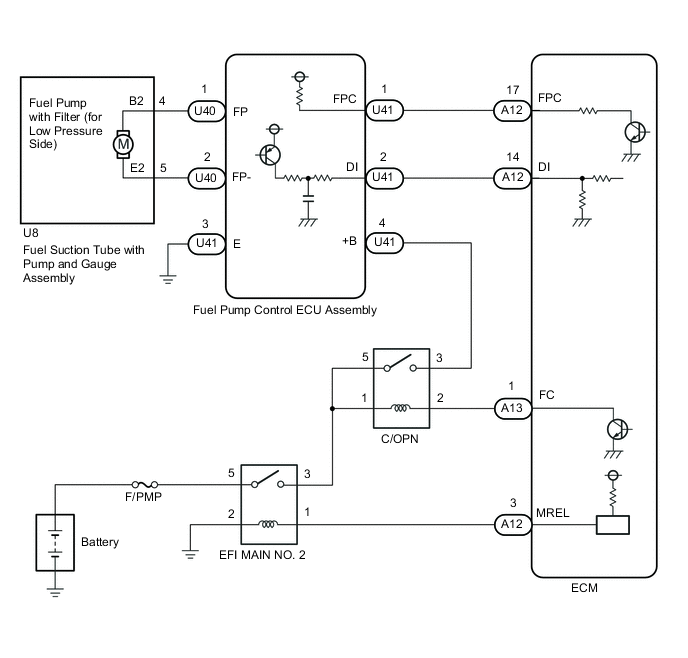
When a malfunction in the fuel pump with filter assembly (for low pressure side) circuit is detected, DTC P0230 is stored. The fuel pump circuit consists of the ECM, fuel pump with filter assembly (for low pressure side) and fuel pump control ECU assembly (which operates the fuel pump). Based on the engine output, the ECM determines the fuel pump speed. The speed is then converted to a duty signal and sent to the fuel pump control ECU assembly. Based on the signal sent from the ECM, the fuel pump control ECU assembly adjusts the fuel pump operation speed between 3 settings. The fuel pump control ECU assembly also has a self-diagnosis function. Based on the fuel pump circuit condition, the fuel pump control ECU assembly outputs a diagnostic signal (DI) to the ECM, and the ECM determines if there is a malfunction in the fuel pump circuit.
| DTC No. | Detection Item | DTC Detection Condition | Trouble Area | MIL | Memory |
|---|---|---|---|---|---|
| P0230 | Fuel Pump Primary Circuit | When either condition below is met (1 trip detection logic):
|
|
Does not come on | DTC stored |
MONITOR DESCRIPTION
To monitor the fuel pump with filter assembly (for low pressure side) circuit, the ECM checks the fuel pump control signal (FPC) and diagnostic signal (DI). The FPC voltage varies between approximately 0 V to approximately 12 V (duty signal). Based on the condition of the fuel pump control ECU assembly malfunction, the DI voltage varies between approximately 0 V and approximately 12 V. The ECM then compares the variance of the FPC voltage and DI voltage, and determines if the fuel pump circuit is malfunctioning. When the ECM determines that the fuel pump circuit is malfunctioning, a DTC is set immediately.
WIRING DIAGRAM
CAUTION / NOTICE / HINT
Note
-
This troubleshooting procedure is based on the premise that the engine is started. If the engine is not started, proceed to the problem symptoms table.
-
Inspect the fuses for circuits related to this system before performing the following procedure.
PROCEDURE
-
CHECK FOR DTC (B1500)
-
Connect the GTS to the DLC3.
-
Turn the engine switch on (IG).
-
Turn the GTS on.
-
Enter the following menus: Body Electrical / Combination Meter / Trouble Codes.
Body Electrical > Combination Meter > Trouble Codes -
Read the DTCs.
Result Result Proceed to DTC B1500 is not output A DTC B1500 is output B
B 
GO TO DTC B1500 Click here
A 
-
-
PERFORM ACTIVE TEST USING GTS (CONTROL THE FUEL PUMP/SPEED)
-
Connect the GTS to the DLC3.
-
Turn the engine switch on (IG).
-
Turn the GTS on.
-
Enter the following menus: Powertrain / Engine / Active Test / Control the Fuel Pump / Speed.
Powertrain > Engine > Active TestTester Display Control the Fuel Pump / Speed -
Check whether operating sounds can be heard while operating the fuel pump with filter assembly (for low pressure side) using the GTS.
OK Operating sounds can be heard from fuel pump with filter assembly (for low pressure side). Result Proceed to OK NG
NG 
INSPECT C/OPN RELAY Click here
OK
-
-
CHECK HARNESS AND CONNECTOR (ECM - FUEL PUMP CONTROL ECU ASSEMBLY - FUEL SUCTION TUBE WITH PUMP AND GAUGE ASSEMBLY)
-
Disconnect the A12 ECM connector.
-
Disconnect the U41 and U40 fuel pump control ECU assembly connectors.
-
Disconnect the U8 fuel suction tube with pump and gauge assembly connector.
-
Measure the resistance according to the value(s) in the table below.
Standard Resistance Tester Connection Condition Specified Condition A12-17 (FPC) - U41-1 (FPC) Always Below 1 Ω A12-14 (DI) - U41-2 (DI) Always Below 1 Ω U40-1 (FP) - U8-4 (B2) Always Below 1 Ω U40-2 (FP-) - U8-5 (E2) Always Below 1 Ω A12-17 (FPC) or U41-1 (FPC) - Body ground Always 10 kΩ or higher A12-14 (DI) or U41-2 (DI) - Body ground and other terminals Always 10 kΩ or higher U40-1 (FP) or U8-4 (B2) - Body ground and other terminals Always 10 kΩ or higher U40-2 (FP-) or U8-5 (E2) - Body ground and other terminals Always 10 kΩ or higher Result Proceed to OK NG
NG
REPAIR OR REPLACE HARNESS OR CONNECTOR
OK
-
-
REPLACE FUEL PUMP CONTROL ECU ASSEMBLY
-
Replace the fuel pump control ECU assembly.
Result Proceed to NEXT
NEXT
-
-
CONFIRM WHETHER DTC OUTPUT RECURS (DTC P0230)
-
Check that there is 17 L or more of fuel remaining.
-
Connect the GTS to the DLC3.
-
Turn the engine switch on (IG).
-
Turn the GTS on.
-
Clear the DTCs.
Powertrain > Engine > Clear DTCs -
Turn the engine switch off and wait for at least 30 seconds.
-
Turn the engine switch on (IG).
-
Turn the GTS on.
-
Cranking it for 15 seconds.
-
Idle it for 1 minute.
-
Enter the following menus: Powertrain / Engine / Trouble Codes.
Powertrain > Engine > Trouble Codes -
Read the DTCs.
Result Result Proceed to DTCs are not output A DTC P0230 is output B
A
END
B
REPLACE ECM Click here
-
-
INSPECT C/OPN RELAY
-
Inspect the C/OPN relay.
Result Proceed to OK NG
NG
REPLACE C/OPN RELAY
OK
-
-
CHECK TERMINAL VOLTAGE (POWER SOURCE OF C/OPN RELAY)
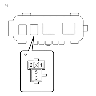
*1 No. 3 Engine Room Relay Block *2 C/OPN Relay Holder
-
Remove the C/OPN relay from the No. 3 engine room relay block.
-
Turn the engine switch on (IG).
-
Measure the voltage according to the value(s) in the table below.
Standard Voltage Tester Connection Switch Condition Specified Condition 1 (C/OPN relay holder) - Body ground Engine switch on (IG) 11 to 14 V 5 (C/OPN relay holder) - Body ground Engine switch on (IG) 11 to 14 V Result Proceed to OK NG
NG
GO TO FUEL PUMP CONTROL CIRCUIT Click here
OK
-
-
CHECK HARNESS AND CONNECTOR (C/OPN RELAY - ECM - FUEL PUMP CONTROL ECU ASSEMBLY)
-
Remove the C/OPN relay from the No. 3 engine room relay block.
-
Disconnect the A13 ECM connector.
-
Disconnect the U41 fuel pump control ECU assembly connector.
-
Measure the resistance according to the value(s) in the table below.
Standard Resistance Tester Connection Condition Specified Condition 2 (C/OPN relay holder) - A13-1 (FC) Always Below 1 Ω 3 (C/OPN relay holder) - U41-4 (+B) Always Below 1 Ω 2 (C/OPN relay holder) or A13-1 (FC) - Body ground and other terminals Always 10 kΩ or higher 3 (C/OPN relay holder) or U41-4 (+B) - Body ground and other terminals Always 10 kΩ or higher Result Proceed to OK NG
NG
REPAIR OR REPLACE HARNESS OR CONNECTOR
OK
-
-
CHECK HARNESS AND CONNECTOR (FUEL PUMP CONTROL ECU ASSEMBLY - FUEL SUCTION TUBE WITH PUMP AND GAUGE ASSEMBLY)
-
Disconnect the U40 fuel pump control ECU assembly connector.
-
Disconnect the U8 fuel suction tube with pump and gauge assembly connector.
-
Measure the resistance according to the value(s) in the table below.
Standard Resistance Tester Connection Condition Specified Condition U40-1 (FP) - U8-4 (B2) Always Below 1 Ω U40-2 (FP-) - U8-5 (E2) Always Below 1 Ω U40-1 (FP) or U8-4 (B2) - Body ground and other terminals Always 10 kΩ or higher U40-2 (FP-) or U8-5 (E2) - Body ground and other terminals Always 10 kΩ or higher Result Proceed to OK NG
NG
REPAIR OR REPLACE HARNESS OR CONNECTOR
OK
-
-
INSPECT FUEL PUMP WITH FILTER ASSEMBLY (FOR LOW PRESSURE SIDE)
-
Inspect the fuel pump with filter assembly (for low pressure side).
Result Proceed to OK NG
NG
REPLACE FUEL PUMP WITH FILTER ASSEMBLY (FOR LOW PRESSURE SIDE) Click here
OK
-
-
CHECK HARNESS AND CONNECTOR (ECM - FUEL PUMP CONTROL ECU ASSEMBLY)
-
Disconnect the A12 ECM connector.
-
Disconnect the U41 fuel pump control ECU assembly connector.
-
Measure the resistance according to the value(s) in the table below.
Standard Resistance Tester Connection Condition Specified Condition A12-17 (FPC) - U41-1 (FPC) Always Below 1 Ω A12-14 (DI) - U41-2 (DI) Always Below 1 Ω U41-3 (E) - Body ground Always Below 1 Ω A12-17 (FPC) OR U41-1 (FPC) - Body ground and other terminals Always 10 kΩ or higher A12-14 (DI) OR U41-2 (DI) - Body ground and other terminals Always 10 kΩ or higher Result Proceed to OK NG
NG
REPAIR OR REPLACE HARNESS OR CONNECTOR
OK
-
-
REPLACE FUEL PUMP CONTROL ECU ASSEMBLY
-
Replace the fuel pump control ECU assembly.
Result Proceed to NEXT
NEXT
-
-
CHECK WHETHER DTC OUTPUT RECURS (DTC P0230)
-
Check that there is 17 L or more of fuel remaining.
-
Connect the GTS to the DLC3.
-
Turn the engine switch on (IG).
-
Turn the GTS on.
-
Clear the DTCs.
Powertrain > Engine > Clear DTCs -
Turn the engine switch off and wait for at least 30 seconds.
-
Turn the engine switch on (IG).
-
Turn the GTS on.
-
Cranking it for 15 seconds.
-
Idle it for 1 minute.
-
Enter the following menus: Powertrain / Engine / Trouble Codes.
Powertrain > Engine > Trouble Codes -
Read the DTCs.
Result Result Proceed to DTCs are not output A DTC P0230 is output B
A
END
B
REPLACE ECM Click here
-