SFI SYSTEM(w/ Canister Pump Module) Air Intake Control Circuit
DESCRIPTION
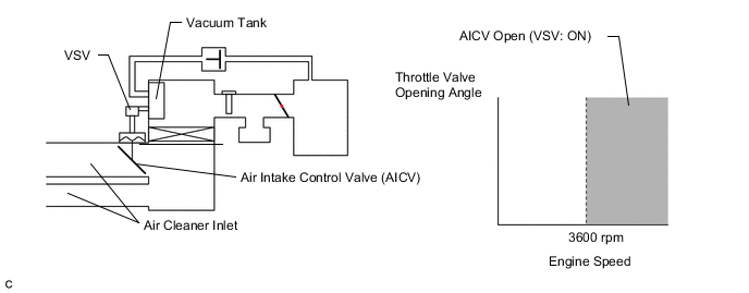
The air cleaner is equipped with two inlets, one of which is opened or closed by the Air Intake Control Valve (AICV). This system reduces intake noise and increases engine power at low-to-high engine speed range. When the engine is operating in the low-to-mid speed range, this control operates the AICV to close one of the air cleaner inlets. When the engine speed is more than 3600 rpm, the ECM activates VSV and opens the AICV.
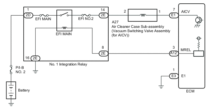
WIRING DIAGRAM
CAUTION / NOTICE / HINT
Note
Inspect the fuses for circuits related to this system before performing the following procedure.
PROCEDURE
-
PERFORM ACTIVE TEST USING GTS (ACTIVATE THE VSV FOR AICS)
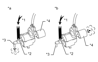
*1 Air *2 Port E *3 Port F *4 Air Filter *a Vacuum Switching Valve is On *b Vacuum Switching Valve is Off
-
Connect the GTS to the DLC3.
-
Turn the engine switch on (IG).
-
Turn the GTS on.
-
Enter the following menus: Powertrain / Engine / Activate / Active Test the VSV for ACIS
Powertrain > Engine > Active TestTester Display Activate the VSV for AICS -
Check for operation of the VSV when the VSV is operated using the GTS.
Standard GTS Connection Specified Condition ON Air from port E flows out through port F OFF Air from port E flows out through the air filter Result Proceed to OK NG
OK 
PROCEED TO NEXT SUSPECTED AREA SHOWN IN PROBLEM SYMPTOMS TABLE Click here
NG 
-
-
INSPECT AIR CLEANER CASE SUB-ASSEMBLY (VACUUM SWITCHING VALVE ASSEMBLY (FOR ACIS))
-
Inspect the air cleaner case sub-assembly (vacuum switching valve assembly (for ACIS)).
Result Proceed to OK NG
NG
REPLACE AIR CLEANER CASE SUB-ASSEMBLY (VACUUM SWITCHING VALVE ASSEMBLY (FOR ACIS)) (FOR AIR INTAKE CONTROL VALVE)
OK
-
-
CHECK TERMINAL VOLTAGE (POWER SOURCE OF AIR CLEANER CASE SUB-ASSEMBLY (VACUUM SWITCHING VALVE ASSEMBLY (FOR ACIS)))
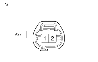
*a Front view of wire harness connector
(to Air Cleaner Case Sub-assembly (Vacuum Switching Valve Assembly (for ACIS))
-
Disconnect the air cleaner case sub-assembly (vacuum switching valve assembly (for ACIS)) connector.
-
Turn the engine switch on (IG).
-
Measure the voltage according to the value(s) in the table below.
Standard Voltage Tester Connection Switch Condition Specified Condition A27-2 - Body ground Engine switch on (IG) 11 to 14 V Result Proceed to OK NG
NG 
CHECK HARNESS AND CONNECTOR (NO. 1 INTEGRATION RELAY - AIR CLEANER CASE SUB-ASSEMBLY (VACUUM SWITCHING VALVE ASSEMBLY (FOR ACIS))) Click here
OK
-
-
CHECK HARNESS AND CONNECTOR (AIR CLEANER CASE SUB-ASSEMBLY (VACUUM SWITCHING VALVE ASSEMBLY (FOR ACIS)) - ECM)
-
Disconnect the A27 air cleaner case sub-assembly (vacuum switching valve assembly (for ACIS)) connector.
-
Disconnect the E1 ECM connector.
-
Measure the resistance according to the value(s) in the table below.
Standard Resistance Tester Connection Condition Specified Condition A27-1 - E1-7 (AICV) Always Below 1 Ω A27-1 or E1-7 - Body ground and other terminals Always 10 kΩ or higher Result Proceed to OK NG
NG
REPAIR OR REPLACE HARNESS OR CONNECTOR
OK
-
-
INSPECT AIR CLEANER ASSEMBLY (VACUUM SURGE TANK)
-
Inspect the vacuum surge tank.
Result Proceed to OK NG
OK
REPLACE ECM Click here
NG
REPAIR OR REPLACE AIR CLEANER ASSEMBLY
-
-
CHECK HARNESS AND CONNECTOR (NO. 1 INTEGRATION RELAY - AIR CLEANER CASE SUB-ASSEMBLY (VACUUM SWITCHING VALVE ASSEMBLY (FOR ACIS)))
-
Remove the No. 1 integration relay from No. 2 engine room relay block.
-
Disconnect the A27 air cleaner case sub-assembly (vacuum switching valve assembly (for ACIS)) connector.
-
Measure the resistance according to the value(s) in the table below.
Standard Resistance Tester Connection Condition Specified Condition 2E-14 - A27-2 Always Below 1 Ω 2E-14 or A27-2 - Body ground and other terminals Always 10 kΩ or higher Result Proceed to OK NG
OK
REPLACE NO. 1 INTEGRATION RELAY Click here
NG
REPAIR OR REPLACE HARNESS OR CONNECTOR
-