SFI SYSTEM(w/ Canister Pump Module), Diagnostic DTC:P0087
| DTC Code | DTC Name |
|---|---|
| P0087 | Fuel Rail / System Pressure - Too Low |
DESCRIPTION
The high-pressure fuel system consists of the spill control valve, pump plunger, check valve, relief valve and fuel pressure sensor. The spill control valve opens and closes the low-pressure fuel line (from the fuel tank), the pump plunger (operated by the camshaft) pressurizes fuel, the check valve mechanically opens and closes the high pressure fuel line (to the fuel delivery pipe), the relief valve prevents fuel pressure from becoming extremely high, and the fuel pressure sensor located on the fuel delivery pipe monitors fuel pressure.
The fuel pump with seal sub-assembly (for high pressure side) is installed to the cylinder head cover (bank 1 and bank 2) and is driven by the cam located at the rear end of the intake camshaft.
The plunger moves up and down by the camshaft rotations, and produces a vacuum to suck fuel and pressurizes the fuel. This fuel then pushes the check valve open and flows into the fuel delivery pipe. The ECM opens and closes the spill control valve to regulate the fuel pressure to the target fuel pressure of 2.5 to 18 MPa (25.5 to 183.5 kgf/cm2, 363 to 2611 psi). In order to obtain and maintain the target pressure, the ECM monitors the fuel pressure using the fuel pressure sensor and performs the feedback control. If the internal fuel pressure of the fuel delivery pipe exceeds the standard pressure of 23.6 MPa (240.6 kgf/cm2, 3423 psi), the fuel relief valve built into the fuel pump with seal sub-assembly (for high pressure side) discharges the fuel pressure.
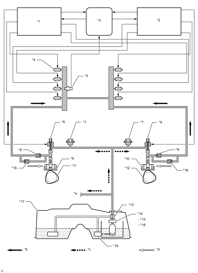
| *1 | No. 1 Injector Driver | *2 | No. 2 Injector Driver |
| *3 | ECM | *4 | Direct fuel injectorassembly |
| *5 | Fuel Delivery Pipe LH (Fuel Pressure Sensor) | *6 | Spill Control Valve |
| *7 | Pulsation Damper | *8 | Check Valve |
| *9 | Fuel Pump with Seal Sub-assembly (for High Pressure Side Bank1) | *10 | Fuel Pump with Seal Sub-assembly (for High Pressure Side Bank2) |
| *11 | Intake Camshaft (for Bank 1) | *12 | Intake Camshaft (for Bank 2) |
| *13 | Pressure Regulator | *14 | Fuel Pump with Filter Assembly (for Low Pressure Side) |
| *15 | Fuel Pump (for Low Pressure Side) | *16 | Fuel Filter |
| *17 | Fuel Tank | *18 | Fuel Relief Valve |
| *19 | Jet Pump | - | - |
| *a | to Fuel Injector Assembly for Port Injection Line | *b | High Pressure Fuel Line |
| *c | Low Pressure Fuel Line | *d | Return Fuel Line |
| DTC No. | Detection Item | DTC Detection Condition | Trouble Area | MIL | Memory |
|---|---|---|---|---|---|
| P0087 | Fuel Rail / System Pressure - Too Low | Although the ECM requests the fuel pump with seal sub-assembly (for high pressure side) opens the spill valve, fuel pressure decreases 5 MPa (51.0 kgf/cm2, 725 psi) from target fuel pressure for about 10 seconds (1 trip detection logic). |
|
Comes on | DTC stored |
MONITOR DESCRIPTION
If the fuel pressure decreases despite an increase request signal being sent to the fuel pump with seal sub-assembly (for high pressure side) by the ECM, the ECM will illuminate the MIL and store this DTC.
MONITOR STRATEGY
| Required Sensors/Components | Fuel delivery pipe LH (fuel pressure sensor) |
| Frequency of Operation | Continuous |
CONFIRMATION DRIVING PATTERN
-
Connect the GTS to the DLC3.
-
Turn the engine switch on (IG).
-
Turn the GTS on.
-
Record the Freeze Frame Data.
-
Clear the DTCs (even if no DTCs are stored, perform the clear DTC procedure).
-
Turn the engine switch off and wait for at least 30 seconds.
-
Turn the engine switch on (IG).
-
Turn the GTS on.
-
Start the engine.
-
Based on engine speed, engine load and other freeze frame data stored in the ECM, reproduce the conditions present when the DTC was stored.
-
Enter the following menus: Powertrain / Engine / Trouble Codes.
-
Read the pending DTCs.
Tech Tips
-
If a pending DTC is output, the system is malfunctioning.
-
If a pending DTC is not output, perform the following procedure.
-
-
Enter the following menus: Powertrain / Engine / Utility / All Readiness.
-
Input the DTC: P0087.
-
Check the DTC judgment result.
GTS Display Description NORMAL
-
DTC judgment completed
-
System normal
ABNORMAL
-
DTC judgment completed
-
System abnormal
INCOMPLETE
-
DTC judgment not completed
-
Perform driving pattern after confirming DTC enabling conditions
N/A
-
Unable to perform DTC judgment
-
Number of DTCs which do not fulfill DTC preconditions has reached ECU memory limit
Tech Tips
-
If the judgment result shows NORMAL, the system is normal.
-
If the judgment result shows ABNORMAL, the system has a malfunction.
-
If the judgment result shows INCOMPLETE or N/A, perform the Confirmation Driving Pattern and check the DTC judgment result again.
-
CAUTION / NOTICE / HINT
Tech Tips
-
Bank 1 refers to the bank that includes the No. 1 cylinder*.
*: The No. 1 cylinder is the cylinder which is farthest from the transmission.
-
Bank 2 refers to the bank that does not include the No. 1 cylinder.
-
Read freeze frame data using the GTS. The ECM records vehicle and driving condition information as freeze frame data the moment a DTC is stored. When troubleshooting, freeze frame data can help determine if the vehicle was moving or stationary, if the engine was warmed up or not, if the air fuel ratio was lean or rich, and other data from the time the malfunction occurred.
PROCEDURE
-
CHECK FUEL LEAK (HIGH OR LOW PRESSURE SIDE)
-
Check around and beneath the vehicle for fuel leaks, fumes, etc.
OK No fuel leaks present. Result Proceed to OK NG
NG 
REPAIR OR REPLACE FUEL LEAK POINT
OK 
-
-
CHECK OTHER DTCS OUTPUT (IN ADDITION TO DTC P0087)
-
Connect the GTS to the DLC3.
-
Turn the engine switch on (IG).
-
Turn the GTS on.
-
Enter the following menus: Powertrain / Engine / Trouble Codes.
Powertrain > Engine > Trouble Codes -
Read the DTCs.
Result Result Proceed to DTC P0087 is output A DTC P0087 and other DTCs are output B Tech Tips
If any DTCs other than P0087 are output, troubleshoot those DTCs first.
B
GO TO DTC CHART Click here
A
-
-
CONFIRM IF VEHICLE HAS RUN OUT OF FUEL IN PAST
-
Has the vehicle run out of fuel in the past?
Result Proceed to YES NO
YES
DTC CAUSED BY RUNNING OUT OF FUEL
NO
-
-
PERFORM ACTIVE TEST USING GTS (CONTROL THE INJECTION WAY)
-
Connect the GTS to the DLC3.
-
Turn the engine switch on (IG).
-
Turn the GTS on.
-
Start the engine and warm it up.
-
Enter the following menus: Powertrain / Engine / Active Test / Control the Injection Way / Direct / Injection Way and Cylinder #1 Misfire Count to Cylinder #8 Misfire Count.
Powertrain > Engine > Active TestActive Test Display Control the Injection Way Data List Display Injection Way Cylinder #1 Misfire Count Cylinder #2 Misfire Count Cylinder #3 Misfire Count Cylinder #4 Misfire Count Cylinder #5 Misfire Count Cylinder #6 Misfire Count Cylinder #7 Misfire Count Cylinder #8 Misfire Count -
Allow the engine to idle.
-
Monitor all of the Misfire Count values that are displayed on the GTS.
Result Injection Way Result Proceed to Direct No misfire counts, or misfire counts occur randomly in all cylinders A Misfire counts occur in a particular cylinder B Tech Tips
Perform "Inspection After Repair" after replacing the direct fuel injector assembly.
B
REPLACE DIRECT FUEL INJECTOR ASSEMBLY Click here
A
-
-
PERFORM ACTIVE TEST USING GTS (CONTROL THE TARGET FUEL PRESSURE)
-
Connect the GTS to the DLC3.
-
Turn the engine switch on (IG).
-
Turn the GTS on.
-
Start the engine.
-
Enter the following menus: Powertrain / Engine / Active Test / Control the Target Fuel Pressure / Ptrl General / Fuel Press.
Powertrain > Engine > Active TestActive Test Display Control the Target Fuel Pressure Data List Display Fuel Press -
Check that the fuel pressure fluctuates when the target fuel pressure changes.
Tech Tips
The Active Test operation lowers the target fuel pressure by 12.5% or increase the target fuel pressure by 24.8%.
Result Result Proceed to Fuel pressure does not rise A Fuel pressure does not fluctuate B Fuel pressure fluctuates C
B
REPLACE FUEL DELIVERY PIPE LH (FUEL PRESSURE SENSOR) Click here
C 
CHECK INJECTOR DRIVER (NO. 1 AND NO. 2) Click here
A
-
-
CHECK FUEL PUMP OPERATION (FOR LOW PRESSURE SIDE)
-
Check the fuel pump operation (for low pressure side).
Result Proceed to OK NG
NG
GO TO FUEL PUMP CONTROL CIRCUIT Click here
OK
-
-
CHECK FUEL PRESSURE (FOR LOW PRESSURE SIDE)
-
Check the fuel pressure (for low pressure side).
Result Proceed to OK NG
NG
REPAIR OR REPLACE FUEL SYSTEM (PRESSURE REGULATOR, PIPE LINE AND FILTER)
OK
-
-
CHECK INJECTOR DRIVER (NO. 1 AND NO. 2)
-
Turn the engine switch off.
-
Replace the No. 1 and No. 2 injector drivers with known good ones from another vehicle.
Note
Do not disconnect and reconnect the connectors with the engine switch on (IG), as the injector driver (EDU) may be damaged.
-
Connect the GTS to the DLC3.
-
Start the engine.
-
Clear the DTCs.
Powertrain > Engine > Clear DTCs -
Turn the engine switch off and wait for at least 30 seconds.
-
Turn the engine switch on.
-
Turn the GTS on.
-
Perform the driving test.
-
Enter the following menus: Powertrain / Engine / Trouble Codes.
Powertrain > Engine > Trouble Codes -
Read the DTCs.
Result Result Proceed to DTC P0087 is output A DTCs are not output B
B
REPLACE INJECTOR DRIVER (NO. 1 OR NO. 2) Click here
A
-
-
REPLACE FUEL PUMP WITH SEAL SUB-ASSEMBLY (FOR HIGH PRESSURE SIDE)
-
Replace fuel pump with filter assembly (for low pressure side).
Tech Tips
Perform "Inspection After Repair" after replacing the fuel pump with filter assembly (for low pressure side).
Result Proceed to NEXT
NEXT
-
-
CHECK IF DTC OUTPUT RECURS (SEE IF DTC P0087 IS OUTPUT AGAIN)
-
Connect the GTS to the DLC3.
-
Turn the engine switch on (IG).
-
Turn the GTS on.
-
Clear the DTCs.
Powertrain > Engine > Clear DTCs -
Turn the engine switch off and wait for at least 30 seconds.
-
Turn the engine switch on (IG).
-
Turn the GTS on.
-
Drive the vehicle in accordance with the driving pattern described in the Confirmation Driving Pattern.
-
Enter the following menus: Powertrain / Engine / Trouble Codes.
Powertrain > Engine > Trouble Codes -
Read the DTCs.
Result Result Proceed to DTC P0087 is output A DTCs are not output B
A
REPLACE ECM Click here
B
END
-