REAR DISC BRAKE PAD INSTALLATION

PROCEDURE
-
INSTALL REAR DISC BRAKE ANTI-SQUEAL SHIM KIT
-
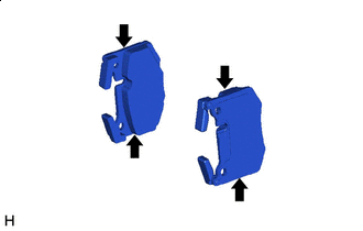

Grease Apply a light coat of disc brake grease to the rear disc brake pads as shown in the illustration.
Note
-
When applying disc brake grease, use the grease enclosed with a rear disc brake pad kit or supplied grease (Part No. 90998-94072) or equivalent.
-
There should be no oil or grease on the friction surfaces of the pads and the disc.
-
-
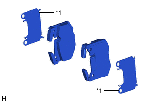
*1 Rear Disc Brake Anti-squeal Shim Install the rear disc brake anti-squeal shim to each rear disc brake pad.
Note
When replacing the rear disc brake pads with new ones, make sure to replace the rear disc brake anti-squeal shim kit at the same time.
-
-
INSTALL REAR DISC BRAKE PAD
-
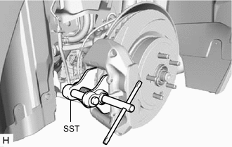
Using SST, push in the rear disc brake piston.
- SST
- 09719-77020
Note
-
Make sure the brake fluid does not overflow from the reservoir.
-
Do not forcibly push in the rear disc brake piston.
-
Check the shape of the rear disc brake pad.
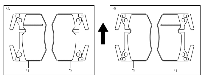
*A for RH side Caliper *B for LH side Caliper *1 Outer Pad *2 Inner Pad Up - - -
Install the pad wear indicator wire assembly to the rear disc brake pad (inner) with a new pad wear indicator retainer.
Note
When replacing the rear disc brake pads with new ones, make sure to replace the pad wear indicator wire assembly and pad wear indicator retainer at the same time.
-
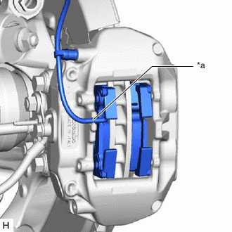
*a Notch Install the 2 rear disc brake pads to the rear disc brake cylinder assembly.
Note
The rear disc brake pad with the pad wear indicator wire assembly must be installed to the inside position.
-
Insert the pad wear indicator wire assembly to the notch of the rear disc brake cylinder assembly.
-
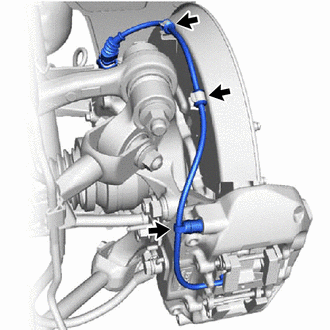
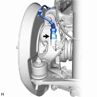
Connect the bleeder plug cap portion of the pad wear indicator wire assembly to the rear disc brake bleeder plug.
-
Install the pad wear indicator wire assembly to the 2 clamps of rear disc brake dust cover.
-
Connect the pad wear indicator wire connector to the rear speed sensor.
-
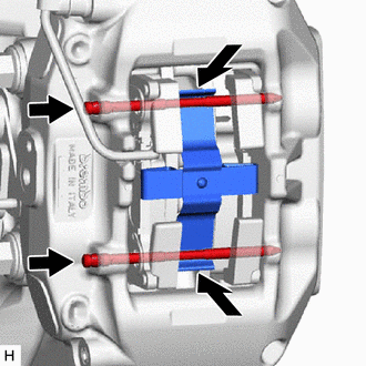
Install the rear disc brake anti-rattle spring to the rear disc brake cylinder assembly.
-
While pushing the rear disc brake anti-rattle spring as shown in the illustration, install the 2 pad guide pins to the rear disc brake cylinder assembly.
-
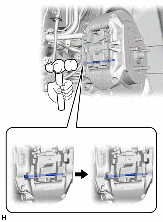
Using a hammer, install the pad guide pin (lower) by tapping the head of the pad guide pin (lower) until the ring is seated in the rear disc brake cylinder assembly.
Note
-
Do not damage the surface of the rear disc brake cylinder assembly.
-
Make sure that the ring of the pad guide pin (lower) is securely engaged with the rear disc brake cylinder assembly.
-
Make sure that the rear disc brake anti-rattle spring (lower) is securely installed into the grooves of the pad guide pin (lower).
-
-
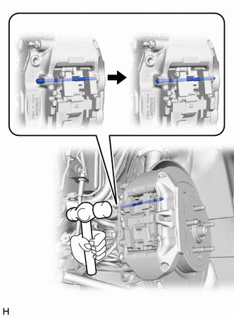
Using a hammer, install the pad guide pin (upper) by tapping the head of the pad guide pin (upper) until the ring is seated in the rear disc brake cylinder assembly.
Note
-
Do not damage the surface of the rear disc brake cylinder assembly.
-
Make sure that the ring of the pad guide pin (upper) is securely engaged with the rear disc brake cylinder assembly.
-
Make sure that the rear disc brake anti-rattle spring (upper) is securely installed into the grooves of the pad guide pin (upper).
-
-
-
INSPECT BRAKE FLUID LEVEL IN RESERVOIR
-
INSTALL FRONT WHEEL