FRONT DISC BRAKE PAD INSTALLATION

CAUTION / NOTICE / HINT
Tech Tips
-
The following procedure is for the LH side.
-
Use the same procedure for the RH side and LH side.
PROCEDURE
-
INSTALL FRONT DISC BRAKE ANTI-SQUEAL SHIM KIT
-
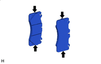

Grease Apply a light coat of disc brake grease to the front disc brake pads as shown in the illustration.
Note
-
When applying disc brake grease, use the grease enclosed with a front disc brake pad kit or supplied grease (Part No. 90998-94072) or equivalent.
-
There should be no oil or grease on the friction surfaces of the pads and the disc.
-
-
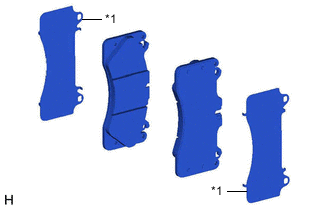
*1 Front Disc Brake Anti-squeal Shim Install the front disc brake anti-squeal shim to each front disc brake pad.
Note
When replacing the front disc brake pads with new ones, make sure to replace the front disc brake anti-squeal shim kit at the same time.
-
-
INSTALL FRONT DISC BRAKE PAD
-
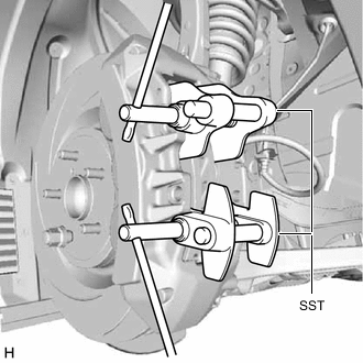
Using SST, push in the front disc brake piston.
- SST
- 09719-77010
Note
-
Make sure the brake fluid does not overflow from the reservoir.
-
Do not forcibly push in the front disc brake piston.
-
Install the pad wear indicator wire assembly to the front disc brake pad (inner) with a new pad wear indicator retainer.
Note
When replacing the front disc brake pads with new ones, make sure to replace the pad wear indicator wire assembly and pad wear indicator retainer at the same time.
-
Install the 2 front disc brake pads to the disc brake cylinder assembly.
Note
The front disc brake pad with the pad wear indicator wire assembly must be installed to the inside position.
-
Insert the pad wear indicator wire assembly to the notch of the disc brake cylinder assembly.
-
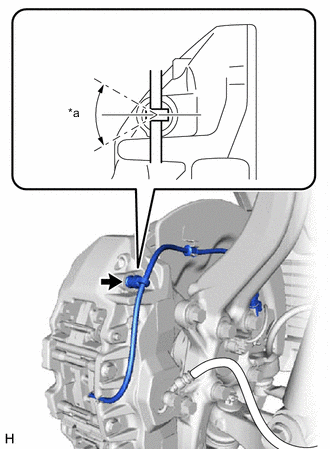
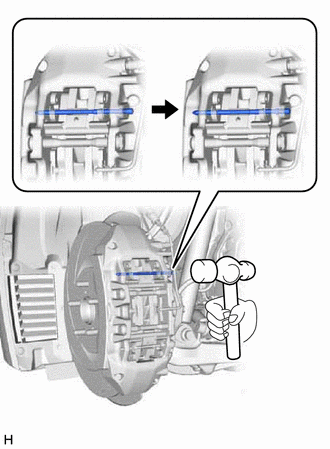
*a 0° +/- 30° Connect the bleeder plug cap portion of the pad wear indicator wire assembly to the front disc brake bleeder plug as shown in the illustration.
Note
Perform this step without the pad wear indicator wire assembly installed to the front disc brake dust cover clamp.
-
Connect the pad wear indicator wire assembly to the clamp of front disc brake dust cover.
-
Connect the pad wear indicator wire connector to the front skid control sensor wire.
-
Install the 2 pad guide tie rods with the 2 bolts.
- Torque:
- 30 N*m { 306 kgf*cm, 22 ft.*lbf }
-
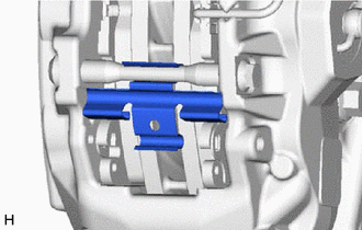
Install the front disc brake anti-rattle spring (lower) to the pad guide tie rod.
-
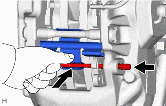
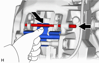
While pushing the front disc brake anti-rattle spring (lower) as shown in the illustration, install the pad guide pin (lower) to the disc brake cylinder assembly.
-
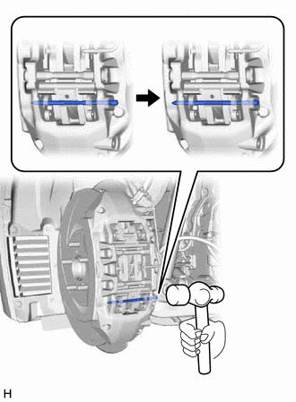
Using a hammer, install the pad guide pin (lower) by tapping the head of the pad guide pin (lower) until the ring is seated in the disc brake cylinder assembly.
Note
-
Do not damage the surface of the disc brake cylinder assembly.
-
Make sure that the ring of the pad guide pin (lower) is securely engaged with the disc brake cylinder assembly.
-
Make sure that the front disc brake anti-rattle spring (lower) is securely installed into the grooves of the pad guide pin (lower).
-
-
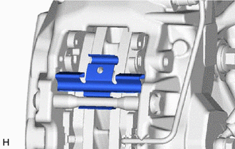
Install the front disc brake anti-rattle spring (upper) to the pad guide tie rod.
-
While pushing the front disc brake anti-rattle spring (upper) as shown in the illustration, install the pad guide pin (upper) to the disc brake cylinder assembly.
-
Using a hammer, install the pad guide pin (upper) by tapping the head of the pad guide pin (upper) until the ring is seated in the disc brake cylinder assembly.
Note
-
Do not damage the surface of the disc brake cylinder assembly.
-
Make sure that the ring of the pad guide pin (upper) is securely engaged with the disc brake cylinder assembly.
-
Make sure that the front disc brake anti-rattle spring (upper) is securely installed into the grooves of the pad guide pin (upper).
-
-
-
INSPECT BRAKE FLUID LEVEL IN RESERVOIR
-
INSTALL FRONT WHEEL