REAR AXLE HUB REMOVAL

CAUTION / NOTICE / HINT
The necessary procedures (adjustment, calibration, initialization, or registration) that must be performed after parts are removed, installed, or replaced during the rear axle hub and bearing assembly removal/installation are shown below.
| Replacement Part or Procedure | Necessary Procedure | Effect/Inoperative when not Performed | Link |
|---|---|---|---|
| Removal/installation of rear disc | Parking brake bedding | Electric parking brake system | |
| Rear wheel alignment adjustment |
|
|
|
| Removal/installation of rear height control sensor sub-assembly | Perform headlight control computer assembly LH initialization | Headlight leveling function |
Tech Tips
-
Use the same procedure for the RH side and LH side.
-
The following procedure is for the LH side.
PROCEDURE
-
REMOVE REAR WHEEL
-
SEPARATE REAR HEIGHT CONTROL SENSOR SUB-ASSEMBLY
-
REMOVE REAR AXLE SHAFT NUT
-
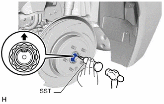
Using SST and a hammer, release the staked part of the rear axle shaft nut.
- SST
- 09930-00010
Note
Loosen the staked part of the nut completely, otherwise the threads of the rear drive shaft assembly may be damaged.
-
While applying the brakes, remove the rear axle shaft nut.
-
-
SEPARATE REAR DISC BRAKE CALIPER ASSEMBLY
-
SEPARATE REAR SPEED SENSOR
-
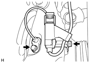
Remove the 2 bolts and separate the rear speed sensor from the rear axle carrier sub-assembly.
Note
-
Prevent foreign matter from contacting the sensor tip.
-
Clean the rear speed sensor installation hole and the contact surfaces every time the rear speed sensor is removed.
-
-
-
REMOVE PARKING BRAKE SHOE ADJUSTING HOLE PLUG
-
REMOVE REAR DISC
-
REMOVE PARKING BRAKE ASSEMBLY
-
REMOVE REAR SUSPENSION ARM COVER
-
SEPARATE REAR STEERING TIE ROD ASSEMBLY
-
SEPARATE REAR NO. 1 SUSPENSION ARM ASSEMBLY
-
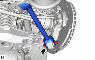
Remove the bolt and nut, and separate the rear No. 1 suspension arm assembly from the rear axle carrier sub-assembly.
Note
Because the nut has its own stopper, do not turn the nut. Loosen the bolt with the nut secured.
-
-
REMOVE REAR STABILIZER LINK ASSEMBLY
-
SEPARATE REAR SHOCK ABSORBER ASSEMBLY
-
REMOVE REAR COIL SPRING
-
REMOVE REAR UPPER COIL SPRING INSULATOR
-
REMOVE REAR LOWER COIL SPRING INSULATOR
-
SEPARATE REAR NO. 1 UPPER CONTROL ARM ASSEMBLY
-
LOOSEN REAR NO. 2 UPPER CONTROL ARM ASSEMBLY
-
REMOVE REAR AXLE ASSEMBLY
-
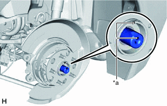
*a Matchmark Put matchmarks on the rear drive shaft assembly and rear axle hub and bearing assembly.
-
Using a plastic hammer, separate the rear drive shaft assembly from the rear axle hub and bearing assembly.
Tech Tips
If it is difficult to separate the rear drive shaft assembly from the rear axle hub and bearing assembly, tap the end of the rear drive shaft assembly using a brass bar and a hammer.
-
Remove the bolt, nut and washer and separate the rear No. 2 upper control arm assembly from the rear axle carrier sub-assembly.
Note
Because the bolt has its own stopper, do not turn the bolt. Loosen the nut with the bolt secured.
-
Remove the rear axle assembly from the rear drive shaft assembly.
Note
Be careful not to damage the rear drive shaft boot.
Tech Tips
Use wire or an equivalent tool to keep the rear drive shaft assembly from hanging down.
-
-
REMOVE REAR NO. 1 WHEEL BEARING DUST DEFLECTOR
-
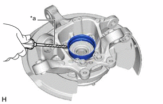
*a Protective Tape Using a screwdriver with its tip wrapped with protective tape, remove the rear No. 1 wheel bearing dust deflector from the rear axle carrier sub-assembly.
Note
Be careful not to damage the rear axle carrier sub-assembly.
-
-
REMOVE REAR AXLE HUB AND BEARING ASSEMBLY
-
Hold the rear axle carrier sub-assembly between aluminum plates in a vise.
Note
Do not overtighten the vise.
-
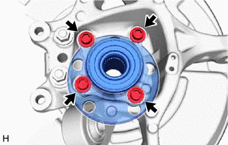
Remove the 4 bolts, parking brake plate sub-assembly and rear axle hub and bearing assembly from the rear axle carrier sub-assembly.
-