TORQUE VECTORING DIFFERENTIAL SYSTEM TERMINALS OF ECU
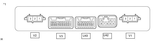
| *1 | Torque Vectoring Differential ECU Assembly | - | - |
| Terminal No. (Symbol) |
Wiring Color | Terminal Description | Condition | Specified Condition |
|---|---|---|---|---|
| U42-1 (PIG) - U42-3 (GND) | B - W-B | Power source (PIG) | Engine switch on (IG) | 11 to 14 V |
| U42-4 (PIG1) - U42-3 (GND) | B - W-B | Power source (PIG) | Engine switch on (IG) | 11 to 14 V |
| U43-1 (CA1H) - U42-3 (GND) | L - W-B | CAN communication signal | Engine switch on (IG) | Pulse generation (Waveform 1) |
| U43-3 (CA3H) - U42-3 (GND) | G - W-B | CAN communication signal | Engine switch on (IG) | Pulse generation (Waveform 2) |
| U43-5 (TVDS) - U42-3 (GND) | V - W-B | TVD mode control signal | Engine switch on (IG), combination switch assembly (TVD Switch) operated | 0 to 3.0 V |
| U43-7 (PIGR) - U42-3 (GND) | W - W-B | TVD relay drive signal | Engine switch on (IG) | 0 to 1.5 V |
| U43-9 (CA1L) - U42-3 (GND) | W - W-B | CAN communication signal | Engine switch on (IG) | Pulse generation (Waveform 1) |
| U43-11 (CA3L) - U42-3 (GND) | SB - W-B | CAN communication signal | Engine switch on (IG) | Pulse generation (Waveform 2) |
| U43-14 (IG1) - U42-3 (GND) | P - W-B | Power source (IG) | Engine switch on (IG) | 11 to 14 V |
| U43-16 (BATT) - U42-3 (GND) | LG - W-B | Power source | Engine switch on (IG) | 11 to 14 V |
| V1-1 (MUR) - U42-3 (GND) | B - W-B | TVD motor drive signal (RH side) | Engine switch on (IG) | Pulse generation (Waveform 3) |
| V1-2 (MVR) - U42-3 (GND) | W - W-B | TVD motor drive signal (RH side) | Engine switch on (IG) | Pulse generation (Waveform 3) |
| V1-3 (MWR) - U42-3 (GND) | R - W-B | TVD motor drive signal (RH side) | Engine switch on (IG) | Pulse generation (Waveform 3) |
| V2-1 (MUL) - U42-3 (GND) | B - W-B | TVD motor drive signal (LH side) | Engine switch on (IG) | Pulse generation (Waveform 4) |
| V2-2 (MVL) - U42-3 (GND) | W - W-B | TVD motor drive signal (LH side) | Engine switch on (IG) | Pulse generation (Waveform 4) |
| V2-3 (MWL) - U42-3 (GND) | R - W-B | TVD motor drive signal (LH side) | Engine switch on (IG) | Pulse generation (Waveform 4) |
| V3-1 (RSNR) - V3-2 (GSNR) | L - R | TVD motor resolver signal (RH side) | Engine switch on (IG) | Pulse generation (Waveform 5) |
| V3-4 (RRFR) - V3-14 (GRFR) | W - Y | TVD motor resolver signal (RH side) | Engine switch on (IG) | Pulse generation (Waveform 5) |
| V3-5 (OTRG) - V3-15 (OTR) | P - V | TVD motor temperature signal (RH side) | Engine switch on (IG) | Pulse generation (Waveform 6) |
| V3-6 (OTL) - V3-16 (OTLG) | B-W - GR | TVD motor temperature signal (LH side) | Engine switch on (IG) | Pulse generation (Waveform 6) |
| V3-7 (GRFL) - V3-17 (RRFL) | Y - W | TVD motor resolver signal (LH side) | Engine switch on (IG) | Pulse generation (Waveform 7) |
| V3-9 (GSNL) - V3-10 (RSNL) | R - L | TVD motor resolver signal (LH side) | Engine switch on (IG) | Pulse generation (Waveform 7) |
| V3-11 (RCSR) - V3-12 (GCSR) | B - G | TVD motor resolver signal (RH side) | Engine switch on (IG) | Pulse generation (Waveform 5) |
| V3-19 (GCSL) - V3-20 (RCSL) | G - B | TVD motor resolver signal (LH side) | Engine switch on (IG) | Pulse generation (Waveform 7) |
-
Oscilloscope waveforms
Tech Tips
Oscilloscope waveform samples are provided here for informational purposes. Noise and fluttering waveforms have been omitted.
-
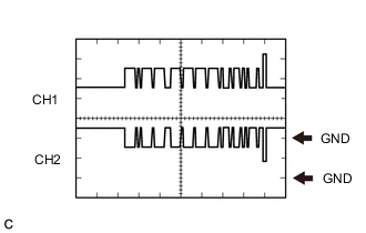
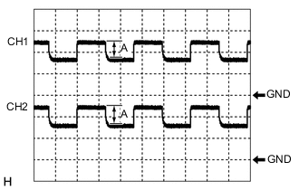
Waveform 1 (CAN communication signal)
Item Content Terminal CH1: U43-1 (CA1H) ←→ U42-3 (GND)
CH2: U43-9 (CA1L) ←→ U42-3 (GND)
Equipment Setting 1 V/DIV., 50 μs./DIV. Condition Engine switch on (IG) Tech Tips
The waveform will vary depending on the content of the digital communication (digital signal).
-
Waveform 2 (CAN communication signal)
Item Content Terminal CH1: U43-3 (CA3H) ←→ U42-3 (GND)
CH2: U43-11 (CA3L) ←→ U42-3 (GND)
Equipment Setting 1 V/DIV., 50 μs./DIV. Condition Engine switch on (IG) Tech Tips
The waveform will vary depending on the content of the digital communication (digital signal).
-
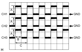
Waveform 3 (TVD motor drive signal (RH side))
Item Content Terminal CH1: V1-1 (MUR) ←→ U42-3 (GND)
CH2: V1-2 (MVR) ←→ U42-3 (GND)
CH3: V1-3 (MWR) ←→ U42-3 (GND)
Equipment Setting CH1, 2, 3: 10 V/DIV., 50 μs./DIV. Condition Engine switch on (IG) Tech Tips
-
The waveform will vary depending on the content of the digital communication (digital signal).
-
The value (A) changes in accordance with the battery voltage.
-
The value (B) changes in accordance with the vehicle condition.
-
C: 100 μs
-
-
Waveform 4 (TVD motor drive signal (LH side))
Item Content Terminal CH1: V2-1 (MUL) ←→ U42-3 (GND)
CH2: V2-2 (MVL) ←→ U42-3 (GND)
CH3: V2-3 (MWL) ←→ U42-3 (GND)
Equipment Setting CH1, 2, 3: 10 V/DIV., 50 μs./DIV. Condition Engine switch on (IG) Tech Tips
-
The waveform will vary depending on the content of the digital communication (digital signal).
-
The value (A) changes in accordance with the battery voltage.
-
The value (B) changes in accordance with the vehicle condition.
-
C: 100 μs
-
-
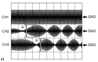
Waveform 5 (TVD motor resolver signal (RH side))
Item Content Terminal CH1: V3-4 (RRFR) ←→ V3-14 (GRFR)
CH2: V3-1 (RSNR) ←→ V3-2 (GSNR)
CH3: V3-11 (RCSR) ←→ V3-12 (GCSR)
Equipment Setting CH1: 2 V/DIV., 5 ms./DIV.
CH2, 3: 500 mV/DIV., 5 ms./DIV.
Condition Engine switch on (IG) Tech Tips
-
The waveform will vary depending on the content of the digital communication (digital signal).
-
The value (A) changes in accordance with the position of the rotor of the TVD motor.
-
-
Waveform 6 (TVD motor temperature signal)
Item Content Terminal CH1: V3-5 (OTRG) ←→ V3-15 (OTR)
CH2: V3-6 (OTL) ←→ V3-16 (OTLG)
Equipment Setting CH1, 2: 2 V/DIV., 100 ms./DIV. Condition Engine switch on (IG) Tech Tips
-
The waveform will vary depending on the content of the digital communication (digital signal).
-
The value (A) changes in accordance with the oil temperature.
-
-
Waveform 7 (TVD motor resolver signal (LH side))
Item Content Terminal CH1: V3-7 (GRFL) ←→ V3-17 (RRFL)
CH2: V3-9 (GSNL) ←→ V3-10 (RSNL)
CH3: V3-19 (GCSL) ←→ V3-20 (RCSL)
Equipment Setting CH1: 2 V/DIV., 5 ms./DIV.
CH2, 3: 500 mV/DIV., 5 ms./DIV.
Condition Engine switch on (IG) Tech Tips
-
The waveform will vary depending on the content of the digital communication (digital signal).
-
The value (A) changes in accordance with the position of the rotor of the TVD motor.
-
-