REAR DRIVE SHAFT ASSEMBLY REMOVAL

CAUTION / NOTICE / HINT
The necessary procedures (adjustment, calibration, initialization, or registration) that must be performed after parts are removed, installed, or replaced during the rear drive shaft assembly removal/installation are shown below.
| Replacement Part or Procedure | Necessary Procedure | Effect/Inoperative when not Performed | Link |
|---|---|---|---|
| Rear wheel alignment adjustment |
|
|
|
| Removal/installation of rear disc | Parking brake bedding | Electric parking brake system |
PROCEDURE
-
REMOVE REAR SUSPENSION MEMBER BRACE LH
-
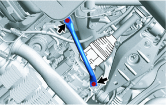
Remove the 2 bolts and rear suspension member brace LH.
-
-
REMOVE REAR SUSPENSION MEMBER BRACE RH
Tech Tips
Use the same procedure as for the LH side.
-
REMOVE REAR AXLE ASSEMBLY LH
-
REMOVE REAR AXLE ASSEMBLY RH
Tech Tips
Use the same procedure as for the LH side.
-
DRAIN TORQUE TRANSFER MODULE FLUID
-
REMOVE REAR DRIVE SHAFT ASSEMBLY LH
-
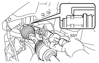
Using SST, remove the rear drive shaft assembly LH.
- SST
- 09520-01010
- 09520-24010 ( 09520-32040 )
Note
-
Be careful not to damage the rear drive shaft oil seal, inboard joint boot and drive shaft dust cover.
-
Be careful not to drop the drive shaft assembly.
-
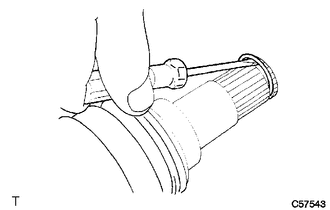
Using a screwdriver, remove the shaft snap ring.
-
-
REMOVE REAR DRIVE SHAFT ASSEMBLY RH
Tech Tips
Use the same procedure as for the LH side.