REAR AXLE HUB INSTALLATION

CAUTION / NOTICE / HINT
Tech Tips
-
Use the same procedure for the RH side and LH side.
-
The following procedure is for the LH side.
PROCEDURE
-
INSTALL REAR AXLE HUB AND BEARING ASSEMBLY
-
Hold the rear axle carrier sub-assembly between aluminum plates in a vise.
Note
Do not overtighten the vise.
-
Install the rear axle hub and bearing assembly and parking brake plate sub-assembly to the rear axle carrier sub-assembly with the 4 bolts.
- Torque:
- 75 N*m { 765 kgf*cm, 55 ft.*lbf }
-
-
INSTALL REAR NO. 1 WHEEL BEARING DUST DEFLECTOR
-
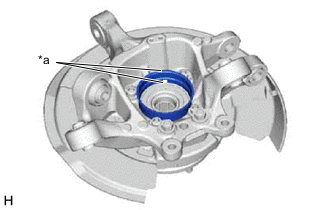
*a Hole Set a new rear No. 1 wheel bearing dust deflector to the rear axle carrier sub-assembly while aligning the hole for the rear speed sensor in the rear No. 1 wheel bearing dust deflector with the hole of the rear axle carrier sub-assembly.
-
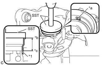
*1 Rear No. 1 Wheel Bearing Dust Deflector *a Hole *b Edge of Rear No. 1 Wheel Bearing Dust Deflector *c Edge of Rear Axle Hub Bearing Outer Race Using SST and a press, install the rear No. 1 wheel bearing dust deflector to the rear axle carrier sub-assembly as specified.
- SST
- 09950-70010 ( 09951-07150 )
- 09951-01000
Standard Length 23.3 to 23.9 mm (0.918 to 0.940 in.)
-
-
INSTALL REAR AXLE ASSEMBLY
-
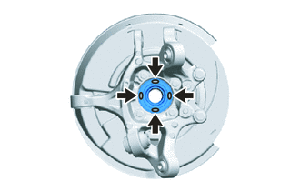
Apply TOYOTA body grease W to the entire contact surface between the rear drive shaft assembly and rear axle hub sub-assembly surface or only apply 0.1 to 0.3 g (0.00353 to 0.0105 oz.) of TOYOTA body grease W to the 4 areas on the axle hub bearing shown in the illustration.
-
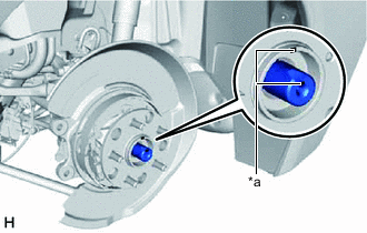
*a Matchmark Install the rear axle assembly to the rear drive shaft assembly.
Note
Align the matchmarks on the rear drive shaft assembly and rear axle hub and bearing assembly.
-
-
TEMPORARILY INSTALL REAR NO. 2 UPPER CONTROL ARM ASSEMBLY
-
TEMPORARILY INSTALL REAR NO. 1 UPPER CONTROL ARM ASSEMBLY
-
INSTALL REAR LOWER COIL SPRING INSULATOR
-
INSTALL REAR UPPER COIL SPRING INSULATOR
-
INSTALL REAR COIL SPRING
-
TEMPORARILY INSTALL REAR SHOCK ABSORBER ASSEMBLY
-
INSTALL REAR STABILIZER LINK ASSEMBLY
-
TEMPORARILY INSTALL REAR NO. 1 SUSPENSION ARM ASSEMBLY
-
Temporarily install the rear No. 1 suspension arm assembly to the rear axle carrier sub-assembly with the bolt and nut.
Note
Because the nut has its own stopper, do not turn the nut. Tighten the bolt with the nut secured.
Tech Tips
Insert the bolt with the threaded end facing the front of the vehicle.
-
-
CONNECT REAR STEERING TIE ROD ASSEMBLY
-
INSTALL PARKING BRAKE ASSEMBLY
-
INSTALL REAR DISC
-
INSTALL REAR DISC BRAKE CALIPER ASSEMBLY
-
Install the rear disc brake caliper assembly with the pad wear indicator wire assembly to the rear axle carrier sub-assembly with the 2 bolts.
- Torque:
- 125 N*m { 1275 kgf*cm, 92 ft.*lbf }
-
-
TEMPORARILY INSTALL REAR AXLE SHAFT NUT
-
Clean the threaded parts on the rear drive shaft assembly and a new rear axle shaft nut using non-residue solvent.
Note
-
Be sure to perform this work even when using a new rear drive shaft assembly.
-
Keep the threaded parts free of oil and foreign matter.
-
-
Using a 32 mm socket wrench, while applying the brakes, temporarily install the rear axle shaft nut.
- Torque:
- 290 N*m { 2957 kgf*cm, 214 ft.*lbf }
Note
Stake the rear axle shaft nut after inspecting for looseness and runout in the following steps.
Tech Tips
Keep depressing the brake pedal to prevent the rear drive shaft assembly from rotating.
-
-
SEPARATE REAR DISC BRAKE CALIPER ASSEMBLY
-
Remove the 2 bolts and separate the rear disc brake caliper assembly with the pad wear indicator wire assembly from the rear axle carrier sub-assembly.
Note
Use wire or an equivalent tool to keep the rear disc brake caliper assembly from hanging by the rear flexible hose.
-
-
REMOVE REAR DISC
-
INSPECT REAR AXLE HUB BEARING LOOSENESS
-
INSPECT REAR AXLE HUB RUNOUT
-
INSTALL REAR DISC
-
INSTALL PARKING BRAKE SHOE ADJUSTING HOLE PLUG
-
INSTALL REAR SPEED SENSOR
-
Install the rear speed sensor to the rear axle carrier sub-assembly with the 2 bolts.
- Torque:
- 8.5 N*m { 87 kgf*cm, 75 in.*lbf }
-
-
INSTALL REAR DISC BRAKE CALIPER ASSEMBLY
-
INSTALL REAR AXLE SHAFT NUT
-
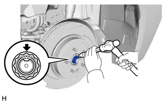
Using a chisel and hammer, stake the rear axle shaft nut.
-
-
STABILIZE SUSPENSION
-
INSTALL REAR NO. 2 UPPER CONTROL ARM ASSEMBLY
-
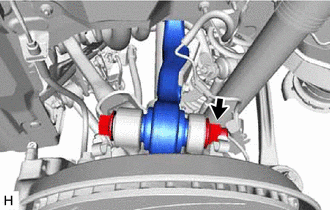
Install the rear No. 2 upper control arm assembly (rear axle assembly side) with the nut.
- Torque:
- 190 N*m { 1937 kgf*cm, 140 ft.*lbf }
Note
Because the bolt has its own stopper, do not turn the bolt. Tighten the nut with the bolt secured.
-
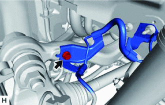
Install the rear speed sensor to the rear No. 2 upper control arm assembly with the bolt.
- Torque:
- 8.5 N*m { 87 kgf*cm, 75 in.*lbf }
-
-
INSTALL REAR NO. 1 UPPER CONTROL ARM ASSEMBLY
-
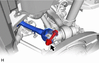
Install the rear No. 1 upper control arm assembly (rear axle assembly side) with the nut.
- Torque:
- 150 N*m { 1530 kgf*cm, 111 ft.*lbf }
Note
Because the bolt has its own stopper, do not turn the bolt. Tighten the nut with the bolt secured.
-
-
INSTALL REAR NO. 2 SUSPENSION ARM ASSEMBLY
-
INSTALL REAR SHOCK ABSORBER ASSEMBLY
-
INSTALL REAR NO. 1 SUSPENSION ARM ASSEMBLY
-
INSTALL REAR SUSPENSION ARM COVER
-
INSTALL REAR HEIGHT CONTROL SENSOR SUB-ASSEMBLY
-
ADJUST PARKING BRAKE
-
INSTALL REAR WHEEL
-
PERFORM PARKING BRAKE SHOE BEDDING
-
INSPECT AND ADJUST REAR WHEEL ALIGNMENT
-
CHECK FOR SPEED SENSOR SIGNAL
-
INITIALIZE HEIGHT CONTROL SENSOR SIGNAL
-
ADJUST HEADLIGHT AIMING