AUTOMATIC TRANSMISSION SYSTEM Shift Paddle Switch Circuit
DESCRIPTION
When the shift lever is in D, operating the "-" side shift paddle switch will cause the transmission to enter fixed range mode which restricts the highest gear. By operating the shift paddle switches "+" (UP) or "-" (DOWN), the shift range can be changed.
When the vehicle is being driven with the shift lever in D (fixed range mode), if the vehicle is stopped or the accelerator pedal is kept steady for a certain period of time with the transmission in the same gear, the vehicle will change back automatically to normal D position operation.
When the shift lever is in M, it is possible to make use of the highest engine speeds by holding the vehicle in a gear. Gear hold control means that gear shifts will not be performed as long as the paddle switches are not operated in either the "+" (UP), or "-" (DOWN) direction.
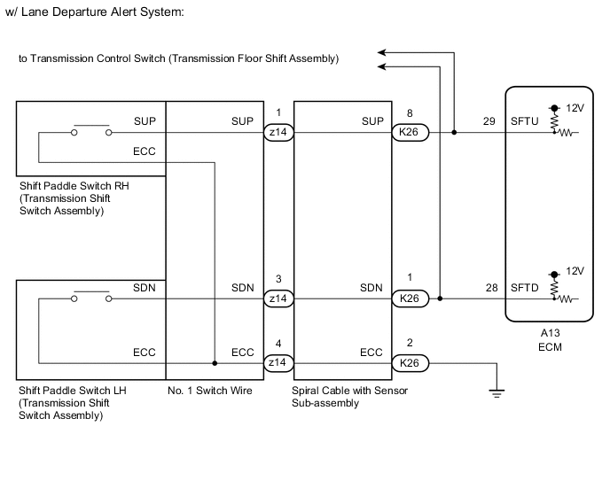
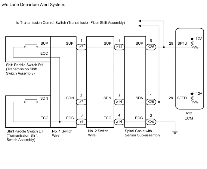
WIRING DIAGRAM
PROCEDURE
-
CHECK HARNESS AND CONNECTOR (SHIFT PADDLE SWITCH - ECM)
-
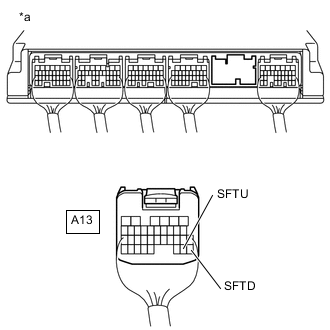
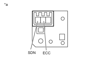
*a Rear view of wire harness connector
(to ECM)
Disconnect the A13 ECM connector.
-
Measure the resistance according to the value(s) in the table below.
Standard Resistance Tester Connection Condition Specified Condition A13-29 (SFTU) - Body ground Pull continuously "+" (Up shift) Below 5.5 Ω Release "+" (Up shift) 1 MΩ or higher A13-28 (SFTD) - Body ground Pull continuously "-" (Down shift) Below 5.5 Ω Release "-" (Down shift) 1 MΩ or higher Result Proceed to OK NG
OK 
PROCEED TO NEXT SUSPECTED AREA SHOWN IN PROBLEM SYMPTOMS TABLE Click here
NG 
-
-
CHECK HARNESS AND CONNECTOR (SPIRAL CABLE WITH SENSOR SUB-ASSEMBLY - BODY GROUND)
-
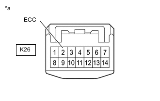
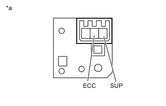
*a Front view of wire harness connector
(to Spiral Cable with Sensor Sub-assembly)
Disconnect the K26 spiral cable with sensor sub-assembly connector.
-
Measure the resistance according to the value(s) in the table below.
Standard Resistance Tester Connection Condition Specified Condition K26-2 (ECC) - Body ground Always Below 1 Ω Result Proceed to OK NG
NG
REPAIR OR REPLACE HARNESS OR CONNECTOR (SPIRAL CABLE WITH SENSOR SUB-ASSEMBLY - BODY GROUND)
OK
-
-
CHECK HARNESS AND CONNECTOR (SPIRAL CABLE WITH SENSOR SUB-ASSEMBLY - ECM)
-
Disconnect the K26 spiral cable with sensor sub-assembly connector.
-
Disconnect the A13 ECM connector.
-
Measure the resistance according to the value(s) in the table below.
Standard Resistance Tester Connection Condition Specified Condition A13-29 (SFTU) - K26-8 (SUP) Always Below 1 Ω A13-28 (SFTD) - K26-1 (SDN) Always Below 1 Ω A13-29 (SFTU) or K26-8 (SUP) - Body ground Always 10 kΩ or higher A13-28 (SFTD) or K26-1 (SDN) - Body ground Always 10 kΩ or higher Result Proceed to OK NG
NG
REPAIR OR REPLACE HARNESS OR CONNECTOR (SPIRAL CABLE WITH SENSOR SUB-ASSEMBLY - ECM)
OK
-
-
INSPECT SPIRAL CABLE SUB-ASSEMBLY
-
Inspect the spiral cable sub-assembly.
Result Proceed to OK NG
NG
REPLACE SPIRAL CABLE SUB-ASSEMBLY Click here
OK
-
-
INSPECT TRANSMISSION SHIFT SWITCH ASSEMBLY (SHIFT PADDLE SWITCH LH)
-
*a Component without harness connected
(Shift Paddle Switch LH (Transmission Shift Switch Assembly))
Remove the transmission shift switch assembly (shift paddle switch LH).
-
Measure the resistance according to the value(s) in the table below.
Standard Resistance Tester Connection Condition Specified Condition SDN - ECC Pull continuously "-" (Down shift) Below 2.5 Ω Release "-" (Down shift) 1 MΩ or higher Result Proceed to OK NG
NG
REPLACE TRANSMISSION SHIFT SWITCH ASSEMBLY (SHIFT PADDLE SWITCH LH) Click here
OK
-
-
INSPECT TRANSMISSION SHIFT SWITCH ASSEMBLY (SHIFT PADDLE SWITCH RH)
-
*a Component without harness connected
(Shift Paddle Switch RH (Transmission Shift Switch Assembly))
Remove the transmission shift switch assembly (shift paddle switch RH).
-
Measure the resistance according to the value(s) in the table below.
Standard Resistance Tester Connection Condition Specified Condition SUP - ECC Pull continuously "+" (Up shift) Below 2.5 Ω Release "+" (Up shift) 1 MΩ or higher Result Result Proceed to OK (w/ Lane Departure Alert System) A OK (w/o Lane Departure Alert System) B NG C
B 
INSPECT NO. 1 SWITCH WIRE Click here
C
REPLACE TRANSMISSION SHIFT SWITCH ASSEMBLY (SHIFT PADDLE SWITCH RH) Click here
A
-
-
INSPECT NO. 1 SWITCH WIRE
-

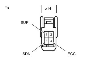
*a Front view of wire harness connector
(No. 1 Switch Wire)
Install the transmission shift switch assembly.
-
Disconnect the No. 1 switch wire connector from the spiral cable with sensor sub-assembly connector.
-
Measure the resistance according to the value(s) in the table below.
Standard Resistance Tester Connection Condition Specified Condition z14-1 (SUP) - z14-4 (ECC) Pull continuously "+" (Up shift) Below 2.5 Ω Release "+" (Up shift) 1 MΩ or higher z14-3 (SDN) - z14-4 (ECC) Pull continuously "-" (Down shift) Below 2.5 Ω Release "-" (Down shift) 1 MΩ or higher Result Proceed to OK NG
OK
PROCEED TO NEXT SUSPECTED AREA SHOWN IN PROBLEM SYMPTOMS TABLE Click here
NG
REPLACE NO. 1 SWITCH WIRE Click here
-
-
INSPECT NO. 1 SWITCH WIRE
-
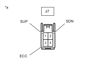
*a Front view of wire harness connector
(No. 1 Switch Wire)
Install the transmission shift switch assembly.
-
Disconnect the No. 1 switch wire connector from the No. 2 switch wire connector.
-
Measure the resistance according to the value(s) in the table below.
Standard Resistance Tester Connection Condition Specified Condition z7-1 (SUP) - z7-3 (ECC) Pull continuously "+" (Up shift) Below 2.5 Ω Release "+" (Up shift) 1 MΩ or higher z7-2 (SDN) - z7-3 (ECC) Pull continuously "-" (Down shift) Below 2.5 Ω Release "-" (Down shift) 1 MΩ or higher Result Proceed to OK NG
NG
REPLACE NO. 1 SWITCH WIRE Click here
OK
-
-
INSPECT NO. 2 SWITCH WIRE
-
*a Front view of wire harness connector
(No. 2 Switch Wire)
Install the No. 1 switch wire connector.
-
Disconnect the No. 2 switch wire connector from the spiral cable with sensor sub-assembly connector.
-
Measure the resistance according to the value(s) in the table below.
Standard Resistance Tester Connection Condition Specified Condition z14-1 (SUP) - z14-4 (ECC) Pull continuously "+" (Up shift) Below 2.5 Ω Release "+" (Up shift) 1 MΩ or higher z14-3 (SDN) - z14-4 (ECC) Pull continuously "-" (Down shift) Below 2.5 Ω Release "-" (Down shift) 1 MΩ or higher Result Proceed to OK NG
OK
PROCEED TO NEXT SUSPECTED AREA SHOWN IN PROBLEM SYMPTOMS TABLE Click here
NG
REPLACE NO. 2 SWITCH WIRE Click here
-