PARK / NEUTRAL POSITION SWITCH INSTALLATION
PROCEDURE
-
INSTALL PARK/NEUTRAL POSITION SWITCH
Tech Tips
Make sure that the manual valve lever shaft has not been rotated prior to installing the park/neutral position switch as the detent spring may become detached from the manual valve lever shaft.
-
Clean the bolt and bolt hole.
-
Apply adhesive to 2 or 3 threads on the end of the bolt.
Adhesive Toyota Genuine Adhesive 1344, Three Bond 1344 or equivalent -
Temporarily install the park/neutral position switch to the automatic transmission assembly with the bolt.
Tech Tips
Tighten the bolt to the specified torque when adjusting the park/neutral position switch.
-
Install the lock washer and lock nut to the park/neutral position switch.
- Torque:
- 6.9 N*m { 70 kgf*cm, 61 in.*lbf }
-
Temporarily install the transmission control shaft lever RH to the manual valve lever shaft with the spring washer and nut.
Tech Tips
Tighten the nut to the specified torque when adjusting the park/neutral position switch.
-
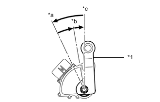
*1 Transmission Control Shaft Lever RH *a P *b R *c N Turn the transmission control shaft lever RH counterclockwise until it stops, then turn it clockwise 2 notches.
-
Remove the nut, spring washer and transmission control shaft lever RH from the manual valve lever shaft.
-
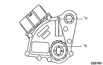
*a Neutral Basic Line *b Groove Align the neutral basic line with the groove as shown in the illustration.
-
Hold the park/neutral position switch in that position and tighten the bolt.
- Torque:
- 12.8 N*m { 131 kgf*cm, 9 ft.*lbf }
-
Using a screwdriver, bend down the tabs of the lock washer.
Tech Tips
Bend at least 2 of the lock washer tabs.
-
Install the transmission control shaft lever RH to the manual valve lever shaft with the spring washer and nut.
- Torque:
- 15.7 N*m { 160 kgf*cm, 12 ft.*lbf }
-
Connect the park/neutral position switch connector.
-
Tilt up the automatic transmission assembly.
-
-
CONNECT REAR ENGINE MOUNTING MEMBER
-
Connect the rear engine mounting member to the vehicle body with the 4 bolts.
- Torque:
- 34.7 N*m { 354 kgf*cm, 26 ft.*lbf }
-
-
INSTALL ENGINE UNDER COVER AIR GUIDE BRACKET
-
Install the engine under cover air guide bracket to the vehicle body with the 2 bolts.
- Torque:
- 25.5 N*m { 260 kgf*cm, 19 ft.*lbf }
-
-
CONNECT FLOOR SHIFT GEAR SHIFTING ROD SUB-ASSEMBLY
-
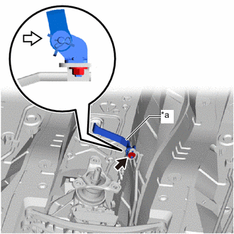
*a Lever 
Push Toward Rear of Vehicle Connect the floor shift gear shifting rod sub-assembly to the lever of the transmission floor shift assembly.
-
Temporarily install the nut to the lever of the transmission floor shift assembly.
-
Tighten the nut while lightly pushing the lever of the transmission floor shift assembly toward the rear of the vehicle.
- Torque:
- 12.8 N*m { 131 kgf*cm, 9 ft.*lbf }
Note
Do not push the lever of the transmission floor shift assembly too hard.
-
-
INSTALL PROPELLER SHAFT WITH CENTER BEARING ASSEMBLY
-
INSPECT SHIFT LEVER POSITION
-
INSPECT PARK/NEUTRAL POSITION SWITCH OPERATION